Continue to Site

Welcome to our site!

Electro Tech is an online community (with over 170,000 members) who enjoy talking about and building electronic circuits, projects and gadgets. To participate you need to register. Registration is free. Click here to register now.

  • Welcome to our site! Electro Tech is an online community (with over 170,000 members) who enjoy talking about and building electronic circuits, projects and gadgets. To participate you need to register. Registration is free. Click here to register now.

Taping into buttons

cheapie408

New Member
I have a variable speed pump that does not have wifi and would like to add one.

Found a youtube video of someone taping into the buttons of the controller using a WiFi relay to mimic a button press. Is it safe to assume that most if not all buttons are some forum of dry contact?

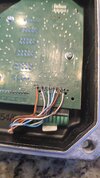
The buttons are connected using a ribbon cable to the board in the photo below. There are a total of 7 buttons on the keypad and a total of 9 pins on the ribbon cable. I measure the current and it appears that it's operating on 5V.

I don't know much about electronics but I'm guessing the keypress should send 5v to whatever the trigger is?

What's the best way to figure out which buttons to press? Would I be measuring for continuity or voltage? 20241020_171444.png20241020_171417.jpg20241020_171410.jpg
 
Last edited:
I don't know much about electronics but I'm guessing the keypress should send 5v to whatever the trigger is?
Sometimes the button is connected to 5v with a resistor. the button connects button to ground when pressed.

Otherwise, the button is connected to ground with a resistor. When the button is pressed, it connects the button to 5v.
 
You need to measure the voltage on the pins while operating the buttons to see what changes as the buttons are pressed and released.
 
Sometimes the button is connected to 5v with a resistor. the button connects button to ground when pressed.

Otherwise, the button is connected to ground with a resistor. When the button is pressed, it connects the button to 5v.

Also such keypads are often multiplexed, so it's not that simple.

Best solution, and works in all cases, is to use a small reed relay to activate the button press, as the relay contacts are completely floating.
 
If you can unplug the keyboard from the unit then test for continuity between the 9 pins. First do this with no buttons pressed. I would expect to find no continuity between any of the 9. Connect one test lead (Say black) to pin 1 then go through touching the red lead on pins 2 to 9 in turn. Next move the black test lead to pin 2 then touch the red lead to pins 3 to 9 in turn. Repeat this until you ave the black lead connected to pin 8 and touching pin 9 with the red lead.
then repeat this process with one button pressed at a time. Create a table of the results and post it so we can work out how it works. As a simple none multiplexed design would only need 8 connections we need to understand why it needs to use 9 wires. Be aware that the contact resistance of membrane keypads can be several hundred ohms.

Les.

I'm glad you said that, I was just about to add it :D

Although, also be aware that the resistance may be too high for the meter to buzz - so you need to watch the display.
 
I have a variable speed pump that does not have wifi and would like to add one.

Found a youtube video of someone taping into the buttons of the controller using a WiFi relay to mimic a button press. Is it safe to assume that most if not all buttons are some forum of dry contact?

The buttons are connected using a ribbon cable to the board in the photo below. There are a total of 7 buttons on the keypad and a total of 9 pins on the ribbon cable. I measure the current and it appears that it's operating on 5V.

I don't know much about electronics but I'm guessing the keypress should send 5v to whatever the trigger is?

What's the best way to figure out which buttons to press? Would I be measuring for continuity or voltage?View attachment 147487View attachment 147488View attachment 147489

Hi,

Another way to do this if the voltages are not too high (and usually they are not) is to use an analog switch.
The analog switch will pass the signals even if they are multiplexed.

I actually did this way back just before home computers (with chess programs) got really popular but after stand -alone chess computers got sort of popular.
For that there were 64 squares and that meant 64 physical switches mounted under the board. When you move a piece you press it down and then move it and press it down again, and the move gets registered by the internal program. I wanted to mimic that functionality using my TRS80 computer with an i/o port. That was so I could record games and play them back on the electronic chess board itself just as if playing a game.
The squares on a chess board are arranged with 8 rows and 8 columns, and the embedded switches are multiplexed, so i had to use 8 analog switches for the rows and 8 for the columns. I also had to detect physical switch depressions so I could record the game being played at the time. The analog switches worked well for mimicking switch closures so the game could be played back automatically by the TRS80 computer.

The analog switches I used where the regular CMOS variety. You get 4 in one IC package if you just need on/off functionality.

A poor imitation of a relay :D

A relay 'WILL' work, an analogue switch 'MAY' work :D
 
So what's strange is I can only get continuity out of 2 wires, I can confirm that when shorting + to those wires does trigger. However, I cannot get continuity out of 3 buttons speed 1, 2, 3 that I really need to tap into.

But at this time, I should be able to at least turn the pump on and off using the one of the wire I found. Is that normal that the buttons react different on the whole panel?

Another I discovered was all but one wire appears to be grounded, I kept constant on the positive and was recording currents on all pins when I moved the ground probe.

If I short the two pin in the box, it triggers the start and stop.

board.png
 
Last edited:
I don't undestand your post #12. I have no idea what is normal on your device.
The tests I requested were with the socket from the keypad to the board unplugged. You then take resistance readings between the connector on the and of the cable from the keypad. As Nigel pointed out DO NOT rely on the continuity range as we do not know at what resistance reading the buzzer changes from off to on. I bought a keypad recently and the contact resistance for some of the buttons was more than 1000 ohms. You will need to find some connector pins to plug into the the connector on the end of the keypad cable to do the tests or get someone to help you by pressing buttons while you hold the meter probes onto the connector pins.

Les.
 
A poor imitation of a relay :D

A relay 'WILL' work, an analogue switch 'MAY' work :D
Hi,

I think the voltage can be up to 15 volts but I don't remember now I'd have to look up the specs.
I like the idea that there is no mechanical movement of parts involved.

You're right though, a relay should always work, I would think.
 
Hi,

I think the voltage can be up to 15 volts but I don't remember now I'd have to look up the specs.
I like the idea that there is no mechanical movement of parts involved.

You're right though, a relay should always work, I would think.

There are various issues because it's not truly isolated, where a relay contact is (up to a pretty silly voltage).
 
Hello everyone, had the time to test this some more, I went through about 40 different wire combination possible and found all the pin combination that responded to the button press. The ohms reading jumps to about between 28-30 initially but usually settle around 25 ohms and drops gradually so I'm calling it 25 ohms for now.

Below is the chart that I made of all pins. I'm only interested in start/stop and V1-V3 (speed)

I know I can start and stop using the relay. According to this, Board Pin 6 is the common pin for speed control. What's throwing it off a little for me is that Board pin 4 and pin 1 also trigger the display/function feature. Is it safe to ignore that according to what this chart is showing? On the board, Pin 1 is far left.
Board Pins.jpg

Board pin 1Board Pin 2Wire 1Wire 2OhmsButton
13OrangeGreen25Up
15OrangeBlue25down
21White/OrangeOrange25Start/Stop
41White/GreenOrange25Display/Function
63White/BlueGreen25V3
64White/BlueWhite/Green25V2
65White/BlueBlue25V1
 
It looks like the buttons are aranged in a 2 x 4 matrix

Matrix.jpg

I think one axis is pins 2 & 6 and the other axis is pins 2,3,4,5.
I think 1 & 6 is the driven axis and 2,3,4,5 is the axis that goes to inputs. (Probably a microcontroller.)
If you look at pins 1 & 6 with an oscilloscope you will finf that theybare being pulsed all the time.
When pin 1 is active the buttons Up, Down, start/Stop and Display function are being read by the microcontroller. When pin 6 is active V1, V2 , V3 are being read. Since the microcontroller is generating the scan pulses it knows the meaning of the 4 inputs for that time slot. You can see from the above diagram how to connect the 7 sets of relay contacts from the remote link.

Les.
 
It looks like the buttons are aranged in a 2 x 4 matrix

View attachment 147526
I think one axis is pins 2 & 6 and the other axis is pins 2,3,4,5.
I think 1 & 6 is the driven axis and 2,3,4,5 is the axis that goes to inputs. (Probably a microcontroller.)
If you look at pins 1 & 6 with an oscilloscope you will finf that theybare being pulsed all the time.
When pin 1 is active the buttons Up, Down, start/Stop and Display function are being read by the microcontroller. When pin 6 is active V1, V2 , V3 are being read. Since the microcontroller is generating the scan pulses it knows the meaning of the 4 inputs for that time slot. You can see from the above diagram how to connect the 7 sets of relay contacts from the remote link.

Les.
Something to add which will probably explain why I measured 5v from pin 6 as well. When the pump is priming, depending on my programmed duration, buttons V1-V3 does not respond. It is only when the priming cycle is completed before I'm able to trigger those buttons.
 
The software in the microcontroller is probably programmed to ignore those buttons for some reason at that time. It MIGHT be possible to use opto isolators instead of relays. You can get 4 opto isolators in a 16 pin DIL package so that would save space. If you use opto isolators that used phototransistors on the output side you may have to add diodes to avoid them conducting when the polarity was reversed.

Les.
 

Latest threads

New Articles From Microcontroller Tips

Back
Top