Continue to Site

Welcome to our site!

Electro Tech is an online community (with over 170,000 members) who enjoy talking about and building electronic circuits, projects and gadgets. To participate you need to register. Registration is free. Click here to register now.

  • Welcome to our site! Electro Tech is an online community (with over 170,000 members) who enjoy talking about and building electronic circuits, projects and gadgets. To participate you need to register. Registration is free. Click here to register now.

Switch schematic.

Status
Not open for further replies.

alphadog

Banned
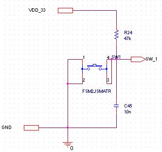
I was suggested to use the next schematic for a switch, which is an interrupt source for MCU.

ui-jpg.27465


I dont understand something.
If you press the switch, then you acctually connect the cap.'s output to GND, wouldnt it cause the capacitor to source a very large spike of current?

Thanks.
 

Attachments

  • ui.JPG
    ui.JPG
    15.3 KB · Views: 253
Yes; it's a bad idea. If it works in practice maybe the inductance of the wires is limiting the current.
Also, good switch contacts have <30mV across them at rated current, so this contact impedance affords you some current limiting.
The current spike is infinitely high with zero time duration but the area under this curve <> zero.
 
The current spike is infinitely high with zero time duration but the area under this curve <> zero.

I don't think you'll have to worry about infinitely high currents in any circuit you build.

The energy held in the capacitor (E = 0.5*C*V^2) is only 54nJ at a low voltage, which is unlikely to hurt your switch.

The circuit shown provides simple debouncing of the switch, attempting to stop your interrupt triggering multiple times from a single press. You may find that you have to increase your time constant depending on the switch.
 
I don't think you'll have to worry about infinitely high currents in any circuit you build.

The energy held in the capacitor (E = 0.5*C*V^2) is only 54nJ at a low voltage, which is unlikely to hurt your switch.
If the switch takes 100 nS to close this would be 1/2w dissipated in the switch contacts for that interval. And I = C dV/dT, with dT being 100 nS, C being 10 nF, dV being 5v?
 
I'm sorry Willbe, but I missed your point. 1/2w doesn't sound like much to me; especially for 100ns. Nor does 0.5Amps for 100ns. The voltage is 3.3v, and I doubt the switch will experience any problems due to the rapid albeit fleeting discharge.

If alphadog is still worried for the sake of the switch, putting a 1k resistor in line with the switch will reduce the maximum current to 3.3mA.
 
But if i put a resistor in the line of the switch i will have a potential divider and my MCU needs to accept HIGH or LOW only, not something in the middle.
 
Have you worked out the voltage of this potential divider? If I'm not mistaken, the value I suggested will give 68mV in the low state - are you saying this is not an acceptable low level range of the input?
 
alphadog check the specs of the I/O line in question, they have very clearly defined voltages levels where the I/O line is guaranteed to be read high and low.
 
I'm sorry Willbe, but I missed your point. 1/2w doesn't sound like much to me; especially for 100ns. Nor does 0.5Amps for 100ns. The voltage is 3.3v, and I doubt the switch will experience any problems due to the rapid albeit fleeting discharge.

If alphadog is still worried for the sake of the switch, putting a 1k resistor in line with the switch will reduce the maximum current to 3.3mA.
I agree, it's not much.
In principle you get an impulse function
Dirac delta function - Wikipedia, the free encyclopedia
when shorting a cap but in practice you can get moderate levels of energy and power dissipated in the switch contacts.
If the switch is rated at 0.5A for 10 million cycles, that's what you'll get.

Next time I'll do the practical calculation along with the textbook ideal.:)
 
Last edited:
Status
Not open for further replies.

Latest threads

New Articles From Microcontroller Tips

Back
Top