rebeccaeazzy
New Member
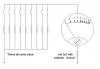
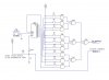
hello, i apologise about the simplicity of the question and my ignorance in electronics but i am trying to design a circuit to count the amount of switches pressed simaltaniously. i would like the circuit to be able to count up to 9 switches and im really not sure of the right components to use. sorry again if its a stupid question. i know i will need a seven segment display and the switches but im afraid thats about it. thanks for your time.

")