Continue to Site

Welcome to our site!

Electro Tech is an online community (with over 170,000 members) who enjoy talking about and building electronic circuits, projects and gadgets. To participate you need to register. Registration is free. Click here to register now.

  • Welcome to our site! Electro Tech is an online community (with over 170,000 members) who enjoy talking about and building electronic circuits, projects and gadgets. To participate you need to register. Registration is free. Click here to register now.

Straight talk about potentiometers

Status
Not open for further replies.

duffman

Member
Well, I am a bit confused about potentiometers. I was wondering if someone could help me out. on schematics they show up as the two on the left.
**broken link removed**
But this is what a pot looks like.
so what goes where?
**broken link removed**

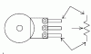
Also I have seen pots with two rows of 5 legs. What the @#%@# is that?!
**broken link removed**


I also have a questoin abou resistors that look like the diagragm all the way on the right of my first pic. what are resistors liek that?! [/img]
 
The first drawing is just a standard symbol for a Pot - the two legs and a wiper. As the Wiper moves the resistance between on leg and the wiper decreaces and the resistance between the wiper and the other leg decreaces. The Center drawing is a standard pot set up to be a variable resistor. The reason the wiper is connected to one of the legs is to set the fail state. This connection eleminates the resistance of the lower part of the pot resistor causing the whole thing to give the resistance of the top part. The fail state, if the wiper fails and disconneccts from the resistor, can be set either to a short or full resistance instead of a floating undefined condition without this type of connection.

The last drawing I havent seen before but it looks like a resistor with a bunch of taps. Like a pot but each tap is evenly spaced giving equal resistance between each step.

The pot with 10 legs is a bit strange It might be a digital encoder instead of a pot. A little testing with your multimeter should help figure our what each pin is doing.

Brent
 
what you have there is a log-pot used for volume control, with a extra tap connection for a "loudness" control. quite common in audio gear.

the extra tap is fixed at a given percentage of the pots range, and is used for a boost circuit that is usually controlled by a switch.

log pot means a pot with a logarithmic taper to its resistance element. this gives a non-linear output from the pot, something needed for audio amps, since you require a "doubling" of the output to sense a change in the perceived volume. the resistance will slowly start to rise, then quickly ramp up to its maximum level.

here is a link with some more info:

https://www.angelfire.com/electronic/funwithtubes/Amp-Volume.html
 
Maybe this will help?
 

Attachments

  • potentiometer_example.gif
    potentiometer_example.gif
    4.7 KB · Views: 382
it would really be best if you simply take multimeter
and try it out. you can only learn, nothing will be damaged.
 
Status
Not open for further replies.

Latest threads

New Articles From Microcontroller Tips

Back
Top