Follow along with the video below to see how to install our site as a web app on your home screen.
Note: This feature may not be available in some browsers.
question 1, no, they are supposed to be reversing relays.,
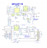
I'm not clear how your circuit is intended to function, but the way the relays are wired the current through L1 is the same direction whichever relay gets energised. Is that correct?
In the .png pic the in/out of U1 have been transposed.
In the Testing Circuit, ++ seems not to be recognised as a voltage source. The positive supply pin of one LT1017 has two labels (14, ++). LTspice doesn't always like that. If you want a node to have two labels, use a jumper (from the Misc folder).
Do you mean the sim? Your schematic says not . Anyway, good you've got the real thing working. Nice job.it seems to be working
The real thing is working great, 25 miles last evening and NO hitches.Do you mean the sim? Your schematic says not . Anyway, good you've got the real thing working. Nice job.
Just by playing with it. When it doesn't do what I expect (which is quite often; I'm still a relative newcomer to simulation) I check the Help . I've also had a lot of assistance, in my early dabbles, from Eric Gibbs: he's the guru.Question, in all sincerity, where did you gain your knowledge of LTSpice workings