Continue to Site

Welcome to our site!

Electro Tech is an online community (with over 170,000 members) who enjoy talking about and building electronic circuits, projects and gadgets. To participate you need to register. Registration is free. Click here to register now.

  • Welcome to our site! Electro Tech is an online community (with over 170,000 members) who enjoy talking about and building electronic circuits, projects and gadgets. To participate you need to register. Registration is free. Click here to register now.

Still killing IRF3205 FETS

Status
Not open for further replies.

kinarfi

Well-Known Member
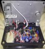
Still killing IRF3205 FETS left and right and I don't know what's wrong:banghead: I have a pile of 19 dead IRF3205 on my table and they all but 2 have the same markings and I'm sure I have smashed and/or trashed about the same amount, I think I got them off eBay and I'm starting to wonder if they are truly International Rectifier or a knock off. When I killed the last one, I had circuit hooked up to a 180 watt, 14v gear motor, one end of the gear motor has the sensor in it, something similar to a Wheatstone Bridge, and the other end is the power output, I held the output shaft with a pair of pliers and turned the input shaft with another pair of pliers while watching the current read out of my power supply, I was getting about 15 amps out when one of the FETs failed shorted, I can only load the gear motor up a little compared to when it's in actual use.
These are 110 amp FETs, 15 amps to a set of paralleled FETs shouldn't be killing them!!!
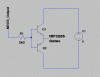
I've brought this up before and tried multiple ways to drive the FETs IR2110, Totems, this time the gate driver was the out from a 555, and they still keep dying and not doing the job.
I gave up on an H Bridge and went to relays to switch the polarity to the motor to save on FETs, while slower, it's plenty fast for what I need and I can concentrate on the FET driver.
Any ideas??? Should I mail the dead FETs to IR so they can see if they're theirs or knock offs.:banghead::banghead::(
Jeff
ps the markings
IRF3205
I R P138D
B9P0
 

Attachments

  • 2014-06-24 POWER STEERING-RELAY+INA122+555 Post.asc
    15.3 KB · Views: 303
  • Untitled.png
    Untitled.png
    58.1 KB · Views: 8,442
Last edited:
What is the "Alternative load"? Obviously they're being shorted somehow. I see in your schematic that you only have a 1Ω resistor separating the FETs from V+, so if your FET "closes" (switches on), then that will be a lot of current flowing through it.
 
What is the FET gate voltage?

What type of heat sink are you using for the FETs? Do they get hot?
 
19 dead IRF3205

That's a lot. What I would do....just me:

1. Source enough to build your project from a completely different supplier...no EBay. All markings must be different/look different to what you have used...Put them in. If they go bang...well than your project has a fault somewhere.

2. If they work as expected...than send the other ones to IR to check for validity...you have to start logically...

Unfortunately, because it is your project...and not a thing you are trying to repair, you could be on a Mission to nowhere.....
The eBay thing always worries me...lot's of rubbish available...But you don't really know because it has never worked properly anyway :(

Nothing to fall back on....and that is hard...gotta start somewhere though :cool:

That's all I can say :(

Regards,
tvtech
 
Last edited:
Things that will kill your Mosfet (a bit generalised) :

Too many volts gate to ground
Spikes from the motor
Too low a rise/drop in gate voltage this will keep the mosfet in linear mode for longer than necessary and cause heating.
Too much heat - as above - not properly driven the mosfets will get hot
Not enough dead time between bridge switching - if both legs of the bridge are on at the same time then you effectively have a short.
Static - I've fried a few in my time by mishandling them.
Flyback diodes which are too slow
Not waiting for the load to stop before reversing it - you can cause massive current spikes with an instant reverse.
Gate oscillation - always try and have a 20-50R series resistor between the gate and the driver.

Hi Pic...

You see the huge picture here though...
Forward gear of reverse...we don't know at this stage..

You see where I am coming from..we really don't know buddy..got to do things logically...and then take it forward...
Mosfets or design or fake parts? We don't know yet. So we are all basically stuffed.

Until we find out :)

Love this,
tvtech
 
Last edited:
Hence why I said it was a bit generalised ;)

The above is to give a bit of an idea to the original poster as to where to look - I notice in his schematic there aren't any gate resistors. This can lead to ringing issues.
 
Hence why I said it was a bit generalised ;)

The above is to give a bit of an idea to the original poster as to where to look - I notice in his schematic there aren't any gate resistors. This can lead to ringing issues.
 
Last edited:
Quote kinarfi, "These are 110 amp FETs, 15 amps to a set of paralleled FETs shouldn't be killing them". No expert, but you are exceeding the "package limit" of the mosfets, even using two of them.

Note #5 on the first or second page of the data sheet says something to the effect of 'package(TO-220) limit is 75W". This is true to any to-220 transistor. It's the "small print" of the data sheet that gets you.

The descripion section on the first page also says, "The TO-220 package is universally preferred for all commercial-industrial applications at power dissipation levels to approximately 50 watts"

https://www.google.com/url?sa=t&rct=j&q=&esrc=s&source=web&cd=1&ved=0CCgQFjAA&url=https://www.irf.com/product-info/datasheets/data/irf3205.pdf&ei=4j6rU4TtHNHF8gHG-YCwBQ&usg=AFQjCNGbcBRs1qJxZ2dF6CEG6nxSCm1kYg&bvm=bv.69620078,d.b2U
 
Hi Kinarfi,
Try interposing the totempole circuit shown in the attached schematic between the 555 pin 3 output and the tied gates of your IRF3205 pair. Q1 & Q2 can be general purpose medium current complementary types, eg 2N3904 for Q1 and 2N3906 for Q2. The problem with directly driving with the NE555 is that the low state output voltage rises with increasing sink current, whereas for properly driving a power NMOSFET (especially a ganged pair as you have) you need both low voltage and high sink current to guarantee turn-off. You can use your present Vdd of 14 V to drive the totem-pole (ie V1 = 14V). Also, looking at your circuit, there appears to be insufficient bypass capacitors to ensure noise-less power rails. I would add at least one 1000uF electrolytic and one 100nF film capacitor at the hot end of R3 and at least one 470uF electrolytic and one 100nF film at the point where each of the relays' electromagnets connects to the +14V supply.
 

Attachments

  • NMOSFET Driver.gif
    NMOSFET Driver.gif
    15.6 KB · Views: 751
What is the "Alternative load"? Obviously they're being shorted somehow. I see in your schematic that you only have a 1Ω resistor separating the FETs from V+, so if your FET "closes" (switches on), then that will be a lot of current flowing through it.
because it takes forever for this to sim, and the time it take for the relays to operate (spice) I eliminate the relays when I run sims, so instead of having the relays, I delete them and use the alternative load. The 1 Ω is actually way high, the motor that I'm trying to drive has an armature resistance of .245Ω and under load, I have seen current in 30 amp range.
 
What is the FET gate voltage?

What type of heat sink are you using for the FETs? Do they get hot?
Gate voltage would be the out from the 555, about 12 volts, on the test I ran today, I had a resistive load of .5Ω and the single IRF3205 got hot, the heat sink used for the commercial set up is a block cast aluminum, but I don't think it's has enough surface area for extended high current use, so I'm going to use a fan cooled block and see if that works.
 
If you connect 12V directly to the gate so the IRF3205 is always on with your test load, does it get as hot?
I'll try that and see what happens.
 
Hi Kinarfi,
Try interposing the totempole circuit shown in the attached schematic between the 555 pin 3 output and the tied gates of your IRF3205 pair. Q1 & Q2 can be general purpose medium current complementary types, eg 2N3904 for Q1 and 2N3906 for Q2. The problem with directly driving with the NE555 is that the low state output voltage rises with increasing sink current, whereas for properly driving a power NMOSFET (especially a ganged pair as you have) you need both low voltage and high sink current to guarantee turn-off. You can use your present Vdd of 14 V to drive the totem-pole (ie V1 = 14V). Also, looking at your circuit, there appears to be insufficient bypass capacitors to ensure noise-less power rails. I would add at least one 1000uF electrolytic and one 100nF film capacitor at the hot end of R3 and at least one 470uF electrolytic and one 100nF film at the point where each of the relays' electromagnets connects to the +14V supply.
On the previous design, I did have a totem, and the output of the NE555 is basically, if not actually a totem and it's built better than I can do. but here's a .png of what I used before with the totem instead of the NE555. I did manage to fry, literally, a FET today, it got so hot that it melted the solder holding the drain lead on so I wrapped the wire and resoldered it then later, it melted the solder on the source lead. I had a temperature probe against the drain held there with shrink tube and the temp was ~ 120C, then it died. I will try mounting the FET to a fan cooled sink and see if that works.
 

Attachments

  • Untitled2.png
    Untitled2.png
    64.3 KB · Views: 862
  • 20140625_212733.jpg
    20140625_212733.jpg
    1.1 MB · Views: 545
Hi Kinarfi,
Please take a look at the circled sections of the attached datasheet excerpts. With reference to the STMicro NE555 datasheet excerpt, you can clearly see that a 100 mA sink current @15V (pretty close to your circuit's +14V Vdd) causes the NE555 pin 3 output voltage to rise to ~2V. Now compare this to the V_gth voltage circled in the IRF3205 datasheet, and draw the obvious conclusion:) !

As regards the NE555 output being a totempole, please refer to the uploaded excerpt from the same STMicro NE555 datasheet, entitled NE555_Schematic, which is the schematic of the innards of the 555.
The circled Q24 in the output cascode is an NPN, whereas for it to be a totempole capable of properly sinking current to turn off the IRF3205 is should be the PNP complement to Q22 (in the same schematic). This explains why the 555 output has problems in both sinking current and staying low voltage in its OFF state. My theory appears to be reasonable, but as always, the proof of the pudding is in the continued survival of the IRF3205's...there' no harm trying is there :D ?[/ATTACH]
NE555_STMicro_Excerpt.gif
NE555_schematic.gif
 

Attachments

  • IRF3205_Excerpt.gif
    IRF3205_Excerpt.gif
    85.9 KB · Views: 568
Last edited:
Are the MOUNTING TABS on the Mosfets INSULATED from the Metal?
These Tabs are Also the DRAIN of the Mosfets.
If they are NOT Insulated, the Metal will Short them OUT.
 
yes, drains are insulated
 
Hi Kinarfi,
Please take a look at the circled sections of the attached datasheet excerpts. With reference to the STMicro NE555 datasheet excerpt, you can clearly see that a 100 mA sink current @15V (pretty close to your circuit's +14V Vdd) causes the NE555 pin 3 output voltage to rise to ~2V. Now compare this to the V_gth voltage circled in the IRF3205 datasheet, and draw the obvious conclusion:) !
Good points, as I see it. the 555 has a better square wave out than the pnp/npn totem in that spice doesn't show an overshoot in the 555 like it does in the pnp/npn totem and the current out drops to 0 very quickly.
One more point, entirely just me, I have the 555 in and already took the the TIP 41c/Tip 42c and I have seen the one of transistor in the totem(npn I think) fry after the fet fails, so I'll stay with the NE555 for now.
 
Status
Not open for further replies.

Latest threads

New Articles From Microcontroller Tips

Back
Top