Continue to Site

Welcome to our site!

Electro Tech is an online community (with over 170,000 members) who enjoy talking about and building electronic circuits, projects and gadgets. To participate you need to register. Registration is free. Click here to register now.

  • Welcome to our site! Electro Tech is an online community (with over 170,000 members) who enjoy talking about and building electronic circuits, projects and gadgets. To participate you need to register. Registration is free. Click here to register now.

Stereo Amp for Mp3 playback.

Status
Not open for further replies.

tblo163

New Member
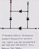
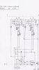
I've just built a stereo amp for Mp3 playback through the rear speakers in my Volvo.(the reason for this was that I was fed up with the various interface units on sale,which do NOT work)The end result is perfect,good sound quality & volume ect.,I used two TDA2003 ICs.,& component values to the Vellerman circuit.with a 47k twin gang volume pot.It works so well I'm making another.This circuit does not require a pre-amp.There's a couple of things I want to explore,although the Vellerman circuit & the Data sheet layout are the same,there is a variation of component values,So I'm wondering how crutial are these values?also what is the purpose of the 1 ohm resistor & 0.1 cap between the output terminals?Any suggestions are welcome. Terry
 

Attachments

  • 7W MONO AMP.pdf
    253.3 KB · Views: 198
  • TDA2003 data.pdf
    230.2 KB · Views: 196
I am very interested in making this amplifier,and will contact you later re-this project.Having read your posts I feel that you could give me some usefull info,
at the moment I am running some low voltage,low ampage applications,MP3 players
for example.And I need a circuit which will ensure the correct polarity to the units
regardless of which input is connected to,this to prevent accidently connecting wrongly
kind regards sw
 
Polarity

Hi SW, O.K. It's easy,you just need 4 diodes(4004 will do,you can probably salvage some from any old circuit) and a small piece of circuit board.
Connect them up as shown in the attachment.It does not matter which is connected to the input of the circuit,the out put will allways remain
the same. glad to help.Terry
 

Attachments

  • bridge.jpg
    bridge.jpg
    2.1 MB · Views: 221
,although the Vellerman circuit & the Data sheet layout are the same,there is a variation of component values,So I'm wondering how crutial are these values?also what is the purpose of the 1 ohm resistor & 0.1 cap between the output terminals?Any suggestions are welcome. Terry
The changes are likely due to some optimization of the values by Vellerman and shouldn't have a significant effect on the circuit operation.

The cap and resistor on the output are to roll off the high frequency impedance to compensate for the increase in impedance from the inductive speaker load. This avoids any circuit oscillation or instabilities that this might otherwise cause.
 
The very old TDA2003 has a puny output power with a 13.2V supply (battery is charged but engine is turned off) of only 4W at clipping into 4 ohms.

Use a newer TDA7240A for 13W.
The TDA1562 has an output of 44W.

The 100nF capacitor in series with a 1 ohm resistor at the output is the load at high frequencies where the inductance of a speaker causes it to be a high impedance and the amplifier oscillates when it has an inductive high impedance load.
 
Hi tblo,I've made the little circuit using the 4 diodes,and it works PERFECT.So now I'm
ready to build your Amp.I have all the components,and would like to install them on a
piece of strip board that I have,it's 64mmX94mm,with 25x37 rails,can you suggest a layout to populate them onto this cb? Thanks for your quick responses, SW
 
Amplifier

Hi Sheila's wheels,glad to hear you've had some success.O.K.You can get
them on the strip board,with plenty of room,I've sent a suggestion,which you can modify if need be.you can space them out to suit your soldering skills,All jumpers to be on the top of the board,and "break" the rails where neccessary.As you will see it's 2 mono amps,giving 2 seperate channels.The two C6 Caps could be replaced by one 2200uF X35V,if you want,but you will
have to modify the jumpers.Any more help? let me know. Good luck Terry.
 

Attachments

  • AMPLIFIER.jpg
    AMPLIFIER.jpg
    3 MB · Views: 150
  • Devil.jpg
    Devil.jpg
    1.1 MB · Views: 307
The diodes reduce the supply voltage to the TDA2003 amplifier so the output is only 3W into 4 ohms instead of 4W.
If the speaker is 8 ohms then the power with a 13.2V battery and the diodes is only 1.6W.
 
Thanks for that.The reason I've been using the TDA2003 is that I have a lot of them & it
seems a shame to waste them,& they don't need a pre-amp.Re; the two ICs that you suggest,I'll look at their data sheets,to see if they need a pre-amp.
 
Two TDA2003 amplifiers can be bridged. Then the output power is 3.5 times more.
Use the circuit that is shown on the TDA2005 datasheet. The huge output coupling capacitor is not needed.

You might need to match the ICs so that there is a small DC voltage across the speaker.
 
Thanks for the quick reply and info.it's the best I've had from anyone,it explains in terms that I can easily understand,without confusing me with too much technical data.
will let you know how I progress,SW;
 
Status
Not open for further replies.

New Articles From Microcontroller Tips

Back
Top