**broken link removed** Thanks dr pepper. I didn't know what I was getting into until I started and then just kept going with it. The whole idea was to use as basic components as possible and ones that I ave available locally. Being a newbie to electronics I want to learn the basics. An if the that was complex here is a circuit including a input for change of direction (the number of parts are surprisingly few though).
Unfortunately I've been traveling for a couple of weeks and haven't had a chance yet to put any of it on aboard to test it out but I will certainly suggestion to clear/preset the flipflops.
I will be using a PLC with the circuit and I want to stay true to the "technology objects" provided by the PLC which basically provides two outputs, one for pulse and the other for direction.
With regard to counters, I did read a couple of designs that included the use of binary counters and I have plans building another stepper drive using that concept as soon as I learn about counters.
Cheers
Kal
Edit:
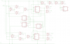
Two Quad NAND gates IC2 and IC3 provide the initial front logic and form part(along with IC5) of the interlock between the two JK flip flops that are part of IC1.
The first three NAND gates of IC2 and IC3 basically make up an AND gates each.
The dual edge trigered D latch IC5A form the main interlock between the JK flipflops of IC1.
IC7A is one of another dual edge triggered D latch and acts as a switch. It presets IC5A and clears IC5B which "turns off" JK flip flop IC1A and "truns on" IC1B.
IC4 IC9 andIC10 are triple three input NAND gates (a dual or quad would've divided even) and form a switch along with IC7B (the secnd of the dual edge triggered D latch) to reverse the direction of the stepper.
Forward direction is logic 0 and actvate the coils in this order: A>B>A'>B'.
Direction reversal is achieved by putting a logic 1 at the direction input to activate the coils in this order: B'>A'>B>A
The sequence of operation is as follows:
Direction is at 0
All flip flops are at cleared state. All Q are zeros and Q' are ones.
1-The first pulse goes to clock input of IC1A and at the same time to all gates of IC9 and to IC10A. Becasue Q of IC1A is 0, IC9A and IC9B lose (result in logic 1)
and becasue directin is 0 IC9C wins (and IC10A loses) and coil A is activated.
2-On pulse tranisiton from high to low, the state of IC1A outputs are changed making Q=1 and Q'=0.
3-The next high pulse comes and hits the same four gates as above only this time IC1A's ouptuts are reversed and directin is still 0 so IC9B wins and activates coil B.
On pulse tranisition from high to low the state of IC1A's outputs are changed again and Q goes back to 0 and Q' goes up to 1. And because Q' is connected to the clock input
of both D latches of IC5 the risiing edge of Q' changes the state of both D latches which turns off IC1A JK flip flop and turns on IC1B JK flip flop.
That in effect sets up coils A' and B" to be actvated by the next two high pulses.
A similar squenece to that in steps 1-3 is repeated for IC1B and its NAND gates IC10B,IC10C,IC4A and IC4B which activate coils A' and B'.
Then on transition of pulse from high to low Q' of IC1B is set back to 1 which edge triggers the clock input of IC7A bringing its Q' low.
IC7A's output Q' will in turn clears IC5A and IC5B which reurns the cycle to its initial state and restart the sequence.
Note that IC7A will be clocked the next time the state of IC1A's Q ouput is changed and as IC7A's D input is now low its ouputs will change to Q=0 and Q'=1
Changing directioin is as simple as raising the direction input to a logic 1 which affects the routing of the pulses through the triple 3-input NAND gates.
.