Continue to Site

Welcome to our site!

Electro Tech is an online community (with over 170,000 members) who enjoy talking about and building electronic circuits, projects and gadgets. To participate you need to register. Registration is free. Click here to register now.

  • Welcome to our site! Electro Tech is an online community (with over 170,000 members) who enjoy talking about and building electronic circuits, projects and gadgets. To participate you need to register. Registration is free. Click here to register now.

some basic questions..

Status
Not open for further replies.

burhanmz

Member
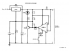
diagram 1 is a 12 battery charger with comparator sense to shut off charging when battery is fully charged

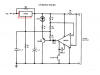
what would happen if i used 2 LM350 parallel to each other with just one configuration for both.. see diagram 2

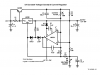
how can i use diagram 3 as an automatic battery charger as in diagram 2.. so that when the battery (12v) is charged a very low current is supplied at reduced voltage as in diagram 2


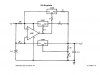
what would happen if i made diagram 4, a buffer sort(i know that isn't possible, there will be difference) and connected if after diagram 1.. so that its a 10A charger but for 12v and with automatic cut off...


and one big thing... i don't understand what the press button switch is for in diagram1 with LM301 to pins 1 and 8.. what does that accomplishes?


and i know i can use a LM338 just as well.. but i can't find any here near home. i want to save the trip to the main market.. so please do answer my questions. thank u.
 

Attachments

  • diag1.PNG
    diag1.PNG
    20.3 KB · Views: 237
  • diag2.PNG
    diag2.PNG
    20.6 KB · Views: 233
  • diag3.PNG
    diag3.PNG
    25.7 KB · Views: 270
  • diag4.PNG
    diag4.PNG
    17.9 KB · Views: 202
The regulators in the 2nd schematic are in parallel. But they are not exactly the same and will not share the current. The one with the highest voltage will hog the load current until it is overloaded then its voltage drops and the 2nd regulator begins to work.

You could probably adjust the circuit in the 3rd schematic to be a battery charger.

The 4th schematic has resistors in series with each regulator that allows them to be connected in parallel and share the load current. The opamp allows the two to be in parallel with the regulator with the opamp. The output current will be much too high to charge a battery.
 
but schematic3 is constant voltage o/p.. even if the battery if fully charged it wouldn't cut off the current to battery.
even if the (when the battery is fully charged) both the battery and LM350 would be at same potential and no current should flow into the battery.. but the battery would have some leakage value, making itself being constantly charged... or wouldn't it?

and i would still like someone to please tell me the use of the press button connected to pin1 of LM301 to ground
 
What type of battery are you charging?
Flooded lead-acid?
Sealed lead-acid?
Other?

(It makes a big difference)
 
...
and i would still like someone to please tell me the use of the press button connected to pin1 of LM301 to ground

Fig 1 is intended for flooded-cell batteries. It implements a two phase charging algorithm. During Phase 1, (LED is ON) the regulator acts as a fixed-voltage current-limited power supply (to 5A) to protect the battery and the regulator when the battery is initially discharged.

When the battery voltage approaches the Charge voltage (probably about 14V, or about 2.3V/cell), the current flow into the battery starts out at 5A, but then naturally decreases as the battery reaches full charge. When the current drops to <~1A, the comparator switches to its other state, which begins Phase 2.

During Phase 2, the LED is OFF. The output voltage is adjusted to the Float Voltage, probably about 13V, which the regulator maintains indefinitely (or until the button is pushed). "Floating" a flooded lead-acid battery at a voltage less than 2.15V/cell will prevent the battery from self-discharging during long periods of inactivity. A flooded-cell Lead-acid battery looses about 10% or its charge per month just sitting around...
 
Sealed lead-acid batteries
12V 40AH and
12V 80AH

and sealed lead acid batteries have a lower leakage than FLA, so i can use schematic 3 as it is?
i think it was u MikeMl who gave me that link to battery charging.. and according to that site i should charge my batteries at 1/10 their AH ratings, but it was also written that SLA could have a higher rating than that (i'm hoping atleast 1/8)

and i have a lot of lm350 's here with me.. that why i was asking if could use somehow schematic 3, and make it like schematic 1 so that it would automatically cut off charging. Is is possible.
 
The two phase algorithm I described in the previous post can be adapted for SLA. The float voltage for FLA is 12.9-13.2V, while for SLA it is 13.13.8V. The peak charging voltage for FLA is 13.9-14.4V, while for SLA it is 14.4-14.7V. The current sensor (shunt and comparator) will work for either battery chemistry. The voltage setting resistors (R1,R3,R4) in Fig 1 would have to be tweaked to make it more suitable for either battery type.
 
Last edited:
Status
Not open for further replies.

Latest threads

New Articles From Microcontroller Tips

Back
Top