Continue to Site

Welcome to our site!

Electro Tech is an online community (with over 170,000 members) who enjoy talking about and building electronic circuits, projects and gadgets. To participate you need to register. Registration is free. Click here to register now.

  • Welcome to our site! Electro Tech is an online community (with over 170,000 members) who enjoy talking about and building electronic circuits, projects and gadgets. To participate you need to register. Registration is free. Click here to register now.

[SOLVED] Discrete BCD Counter Reset

Status
Not open for further replies.

askingNo123

New Member
Hello, i'm new in electronic and i plan to make discrete bcd counter with T flip flop. Before i make it in real, i tried to make it in pspice. But when i pspice it, i found that second flip flop (which count as 2) does not reset when it is 10s (When it counts 1010) and because of it, reset occurs every 8 seconds after first reset. i can't find why it happens and how to solve it. Thanks you for your help.
KakaoTalk_20190525_122504376.png

KakaoTalk_20190525_122504261.png
 
Last edited:
Hi,
can you add the waveform at the emitter of Q19 to the simulation, so the reset logic timing is visible to check that?

A couple of practical problems, which I don't know if the sim will show or not:
The diodes D13 - D16 in the reset circuit will have basically the same voltage drop as the base-emitter junctions of the transistors.
Add the collector voltage of Q17 when that is on and it's dubious whether any reset can happen as the transistors in the bistables may never switch off from Q17.

Possibly connect an extra diode in series with each bistable transistor base, so the input threshold becomes 1.2V? That should guarantee the reset circuit can remove the base drive. Add a high value resistor from base-emitter on each bistable transistor as well, so it definitely turns off with no current through the diode.

You _may_ get away with changing the reset diodes to schottky types, as they have a lower voltage drop.


And, "race conditions" - there is nothing to guarantee a finite duration of the reset pulse, so some bistables may reset (and remove the reset signal) before others respond.

Possibly add a small capacitor from the emitter of Q19 to ground, so Q17 is held on for a definite time after the reset logic gating no longer detects the reset count.

Nice circuit, by the way!


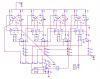
For info, this is a bit of commercial diode-transistor logic, a schematic of a logic board from a 1960s DEC PDP-8 minicomputer:
 
Thanks you for your advice! problem solved!
I put some small capacitor beside Q18 emitter to ground and it works!
and putting resistor between emitter and base make more stable circuit , but i think it not that necessary.
Sorry for late reply. Thank you again!
 

Attachments

  • KakaoTalk_20190529_164723226.png
    KakaoTalk_20190529_164723226.png
    25.5 KB · Views: 228
  • KakaoTalk_20190529_165022283.png
    KakaoTalk_20190529_165022283.png
    153.5 KB · Views: 237
Status
Not open for further replies.

Latest threads

New Articles From Microcontroller Tips

Back
Top