Continue to Site

Welcome to our site!

Electro Tech is an online community (with over 170,000 members) who enjoy talking about and building electronic circuits, projects and gadgets. To participate you need to register. Registration is free. Click here to register now.

  • Welcome to our site! Electro Tech is an online community (with over 170,000 members) who enjoy talking about and building electronic circuits, projects and gadgets. To participate you need to register. Registration is free. Click here to register now.

Solenoid Relay...How The Heck Do I Hook This Thing Up? lol

Status
Not open for further replies.

rs14smith

Member
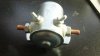
Just for experimenting purposes, I ordered the 36v relay attached in the photo from Amazon here: http://www.amazon.com/gp/product/B004VEPNZ8

Questions:
1. What is the triggering voltage/current and which two terminals control that? It has no label on it what so ever. The box it came in has the the model number: SSMU-1021 and a web address: cncelectrical.com. I went to the address and typed in the model# and got this page: http://www.cncelectrical.com/servlet/the-10936/ELECTRIC-GOLF-CART-STARTER/Detail which also didn't list anything I needed :D

2. Which two terminals are for the load? I assume the brown looking terminals.

Since I don't need this relay for a project of mine anymore I figured I just learn how it works since I already ordered it.
 

Attachments

  • 122_0839.JPG
    122_0839.JPG
    22.4 KB · Views: 196
Last edited:
The small terminals are the coil (36 VDC) and there is no polarity. The large terminals are the contact. It's a typical starter solenoid rated for continuous current.

Ron
 
Hi,

supposedly the two zinc screws are the terminals for the relay coil and the two copper screws are the terminals for the load.

Since its original purpose is a golf cart starter relay I guess the relay contacts are "NO".

You can find out the coil connections using an Ohm-meter. The measured resistance should be in the range of 200 to 400Ω.

Measuring across the copper screws the resistance should be infinitely high.

After that energize the relay using 36VDC. Now the copper screw resistance should be zero Ω (almost).

Boncuk
 
So basically you shouldn't need an external resistor or anything else for the top terminals that trigger the solenoid? For example, if this was a 24v relay and I had 2x batteries, I could just take two leads from the battery and touch the top two terminals and the solenoid would close it's contacts inside and allow current to flow to the load?
 
Last edited:
Hmm it also appears this solenoid will close it's contacts inside off of just 24v. I hooked up 2x 12v batteries to the top terminals, and it allowed current to flow to a LED I had hooked up to the brown big terminals. Is that normal?
 
Yes that is normal.

You might even find it will latch with just 12 volts, but remember as the volts go down the amps go up that it requires to latch the relay.

That is one hell of a relay to drive a led.:)

Pete.
 
Hmm it also appears this solenoid will close it's contacts inside off of just 24v. I hooked up 2x 12v batteries to the top terminals, and it allowed current to flow to a LED I had hooked up to the brown big terminals. Is that normal?

Among the specifications for relay (solenoid) coils is their normal working voltage and two other voltages. Minimum pull in and minimum drop out. Just remember, when the coil pulls in the contacts below its rated voltage the pull isn't as hard. When the contacts are under a load their resistance may be higher due to weaker field strength of the coil. That can be a bad thing. Just something to keep in mind.

Ron
 
When the contacts are under a load their resistance may be higher due to weaker field strength of the coil. That can be a bad thing.
Ron

I don't quite understand. I used to view relays like a gate that slides up and down...like on a castle or better yet, a water valve. Originally I thought that, by supplying only 24v or anything lower, the valve would only open by that amount and only allow that much current to flow. So for example, at 12v, the gate would open maybe 33.3%, at 24v 66.3% and at 36v it would open 100%. If I have a large portion of water (current) behind that valve, there will be a lot of force on the valve (bad) if I only use 12v or 24v, as the valve isn't fully open. However, this doesn't seem to be the case. It appears it works like a digital signal instead of an analog signal. It's either on or off...or open or closed.

So you state it can be a bad thing, but what exactly happens to the solenoid when you do have a load connected to it, and you trigger the solenoid with less than 36v? Does it reduce the life of the internal components inside the solenoid or does it hurt the load some how?
 
Last edited:
Yes that is normal.

You might even find it will latch with just 12 volts, but remember as the volts go down the amps go up that it requires to latch the relay.

Oh I see, so it's kind of a trade off somewhat. At 36v for example, it may only require 1A. At 24v, 2A, and at 12v, 3A...interesting

That is one hell of a relay to drive a led.:)

Haha yeah just needed something to quickly test if it was hooked up correctly or not and to confirm this is a NO relay.
 
OK, I should be out of work soon today and have a Dr. appointment. Then once home we will get into relays in some depth. A relay is an on / off device. Also as to the coil current I don't think you read into what SA posted quite as he intended. If you have an ohm meter measure the DC resistance of the solenoid coil. Lets say you see 360 Ohms. That tells us that with 36 volts applied we get 36 / 360 = 0.1 amp. If I apply 24 volts to that same coil I get 24 / 360 = 0.0666 amps which makes sense and finally if we apply 12 volts we get 12 / 360 = 0.0333 amps so as the vo0ltage decreases so goes the current since the coil value is fixed. Think about it and try a little ohm's law. What I believe SABorn is getting at is the magnetic pull. If I buy a relay with a 360 ohm coil rated for 36 volts fine and well. To get that same coil to do the same job at 24 volts the coil resistance would be decreased to 240 ohms and for 12 volts 120 ohms. But as we reduce the applied voltage to a fixed resistance the current will likewise decrease. A relay's contacts are a switch, they are on or off. I will explain the thing about why running the coil below it's rated voltage a little later.

Ron

Yeah I measured the ohms from the top terminals with a multimeter and I believe it displayed 131ohms or 181ohm I can't remember now. I get the ohms law part, and I guess I see now why at lower voltages it requires "more" current to close the contacts. However, where I'm still a little puzzled is, how is that a bad thing or how does that harm anything?

I wish I was getting off work early today :D
 
That looks like some sort of starter solenoid. What you have to be careful of with those,is duty cycle. That may (or not) be limited duty cycle, in other words it's like the starter in your vehicle, only made to run for short periods of time.
Ther are however some of those that will run for extended periods of time, for example in a 36 volt golf cart, which may be what you have.

Yep, here on the web page it has continuous duty: https://www.amazon.com/gp/product/B004VEPNZ8

Thanks for letting me know that, as I was not aware of that but good to know!
 
what I neglected to mention in my first post was :
An intermittant duty coil will burn out when used for extended periods of time.
 
what I neglected to mention in my first post was :
An intermittant duty coil will burn out when used for extended periods of time.

Well that's great that I have one less thing to worry about then. Just understanding why this thing is fully opening at a lower voltage is a problem of it's own for me, don't need any others coming about. haha

Thanks again!
 
Relays typically have 3 (coil) voltages listed:
Minimum coil pull in = minimum voltage at which the relay will actuate.
Minimum dropout = voltage at which the relay will drop out, usually much less than pull in voltage.
Operating voltage = optimum voltage for consistant, reliable operation, voltage it was designed for.
 
Have you ever put jumper leads on a battery to start a car, and found as you connected the last lead it gave a big spark when you touched the terminal.

Thats an example of large current being drawn, now if you took several goes at connecting the jumper lead it would arc each time and burn some of the jumper clip away with each arc.

If you quickly applied the lead firmly the first time the spark would be small and little or no damage would be done.

Its the same with the switch contacts inside the relay, if they close fast and hard the spark or burning is next to nothing, if they close slowly and chatter a few times when closing the arc and burning is much greater so might damage the switch contacts.

So at 36 volts the contacts slam closed fast and hard, at 12 volt (for a 36 volt rated coil)they will be slower and weak so the risk of arcing and burning is far greater to damage the switch contacts.

A relay is only a on / off device and has no ability to control the amount of power that is permitted to flow through it.
It is a electromechanical switch and nothing more, just the same as any other switch you operate manually, in the case of a relay the coil makes a magnetic field that pulls the metal contacts of the switch together.

Im sure Ron will have a better discription with greater depth when the doc lets him out.

Pete.
 
Relays typically have 3 (coil) voltages listed:
Minimum coil pull in = minimum voltage at which the relay will actuate.
Minimum dropout = voltage at which the relay will drop out, usually much less than pull in voltage.
Operating voltage = optimum voltage for consistant, reliable operation, voltage it was designed for.

Ohhh that's very very helpful. I must be running it between minimum coil pull in and operating voltage.
 
Have you ever put jumper leads on a battery to start a car, and found as you connected the last lead it gave a big spark when you touched the terminal.

Thats an example of large current being drawn, now if you took several goes at connecting the jumper lead it would arc each time and burn some of the jumper clip away with each arc.

If you quickly applied the lead firmly the first time the spark would be small and little or no damage would be done.

Its the same with the switch contacts inside the relay, if they close fast and hard the spark or burning is next to nothing, if they close slowly and chatter a few times when closing the arc and burning is much greater so might damage the switch contacts.

So at 36 volts the contacts slam closed fast and hard, at 12 volt (for a 36 volt rated coil)they will be slower and weak so the risk of arcing and burning is far greater to damage the switch contacts.

A relay is only a on / off device and has no ability to control the amount of power that is permitted to flow through it.
It is a electromechanical switch and nothing more, just the same as any other switch you operate manually, in the case of a relay the coil makes a magnetic field that pulls the metal contacts of the switch together.

Im sure Ron will have a better discription with greater depth when the doc lets him out.

Pete.

Wow that honestly just about cleared up all my confusion and makes perfect sense now! Loving that jumper lead example :D
 
I think that's a good example too. You'll never find a slide switch for high current DC operations for that reason.

Contact design at high voltages incorporate "arc supression". At high currents, there is usually some mechanical separating of contacts too.
 
Status
Not open for further replies.

Latest threads

Back
Top