Continue to Site

Welcome to our site!

Electro Tech is an online community (with over 170,000 members) who enjoy talking about and building electronic circuits, projects and gadgets. To participate you need to register. Registration is free. Click here to register now.

  • Welcome to our site! Electro Tech is an online community (with over 170,000 members) who enjoy talking about and building electronic circuits, projects and gadgets. To participate you need to register. Registration is free. Click here to register now.

Solenoid getting stuck in energized position

Status
Not open for further replies.

pavjayt

Member
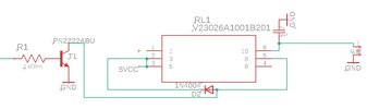
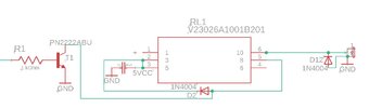
I have a simple design as shown below to drive a set of small self restoring solenoids. Using digital pins on Arduino Mega to toggle them off and on. I have a SN74AS1034AD digital buffer to interface the signals from Mega (pulled down using 10K at the digital buffer input pins) to Solenoid circuitry, while the power to the solenoid is controlled by a relay (RL1)

The issue is that sometimes, random solenoids get stuck in energized state. The voltage across the connector to solenoid stays 5V as soon as I power on the board. I checked the input from Mega, they are at 0V, the output of the buffer stays 0V, but the relay is being turned on which I am not able to understand.

thanks in advance
 

Attachments

  • Screenshot 2022-10-07 133625.jpg
    Screenshot 2022-10-07 133625.jpg
    31 KB · Views: 182
Do you have a flywheel diode across the solenoid as well as across the relay?

You should not really need a buffer to drive a transistor from a normal MCU output.
I can't read the value of the transistor base resistor; is it low enough to ensure the transistor is saturated at the relay current?

It's also good practice to add a base-emitter resistor to any transistor switch to ensure it turns off fully.
 
Thanks for your reply. I updated the schematic screenshot so that the base resistor value is visible. Its a 1K.

I dont have any "flywheel diode" installed across the solenoid. What spec diode would you suggest to use and what value resistor for base-emitter?
 
Have you not learnt how to draw schematics or drive inductive devices yet? Your question and schematic gives no clues to the functional design specs. It appears you chose a dual coil latching relay that requires Set/Reset pulses to drive a solenoid with no specs on all switch interfaces. What power, current voltage , do you need to energize and hold solenoid? Obviously you are damaging drivers without protective clamps for turn-off flyback voltages and EMI issues with CMOS Describe how the design is supposed to work with specs.
 
What spec diode would you suggest to use and what value resistor for base-emitter?
Another 1N4000 series is OK.
The extra resistor could be from 1K to 10K, it's not critical.

The relay needs about 74mA at 5V, so 1K base resistor with 5V drive should be OK - though the data sheet shows base current at 1/10th collector current for hard saturation.

You should remove the 10uF across the solenoid, or add a resistor in series with the cap, as it will effectively short the 5V supply momentarily as the relay switches on and is likely to cause odd effects as well as burn the relay contacts.

It would be better connected to the 5V feed to the relay circuit.

It appears you chose a dual coil latching relay
That relay is a non-latching type, according to the specs?
 
Thanks again rjenkinsgb, I updated the schematic as per your suggestions. See attached, if you have any more suggestions, please let me know
Will be placing those diodes close to the output connectors to solenoids.
 

Attachments

  • Screenshot 2022-10-10 131319.jpg
    Screenshot 2022-10-10 131319.jpg
    43.1 KB · Views: 176
You should still have a resistor from the base of the transistor to ground, around 10k. This prevents any "power bump" from the micro turning it on and the the micro goes to high impedance, leaving the transistor on. The grounding resistor ensures the transistor is off until there is a sustained current to the base.
 
Thanks for you suggestion sagor1. Will implement it as well.
 

Attachments

  • Screenshot 2022-10-10 195649.jpg
    Screenshot 2022-10-10 195649.jpg
    58 KB · Views: 159
The circuit looks OK at that.
What rating is the power supply you are using?

The solenoids take almost an amp each; the power wiring for those (the "load side" of the relays) really needs to connected to the PSU separately from the low current electronics supply and ground, so the voltage to the electronics is not affected by high currents or noise spikes in shared wires; two completely separate circuits, other than then both connecting to the same PSU.

ps. If you used appropriate logic level MOSFETs you should be able to drive the solenoids directly from the Arduino, without the relays or buffer IC, but the wiring layout is then rather more critical.
 
Thanks again, the power supply being used is R78B5.0-1.0

The solenoids are only turned on or off one by one, never all at once.

Here are couple of screenshots of the board layout, its a simple 2-layer board. All heavy traces are for 5V to the load. The input power supply is a 9V switching supply.
 
Last edited:
If something confusing. In the datasheet, the pinout is TOP VIEW, as seen on the PCB. Without knowing which direction is which, looking at RL1, D2 seems it is backwards across the coil, as pin 3 (bottom middle) is the +ve end, and pin 8 (top middle) is the -ve end.
But, it is hard to tell from the PCB which way is pins 1,10 - is it to the left or to the right?
If to the right, then D2 is correct, as are pins 3 and 8. If so, make sure RL4 is mounted the right way, as it is in a reversed direction from RL1.
There should be some marking on the PCB to designate "pin 1" for the relays, too easy to put them in reversed.
 
they are at 0V, the output of the buffer stays 0V, but the relay is being turned on which I am not able to understand.

When the coil current voltage is 0 but the NO contacts are closed, it means the contacts are stuck together from excessive prior corona created by rapid cutoff of an inductive load. When V=LdI/dt exceeds the gap breakdown voltage (BDV) for at least 1 us, an arc occurs. THe gap starts small so with at least 1kV/mm arc, it can be stretched with low voltage drop as the contact tries to go open.

Inspect your relay contact for damage when this occurs and use a flyback diode across each inductive element. The coil does not need a 1N400x and could use a 1N4148
Non−repetitive Peak Forward Surge Current 1.0 A
Pulse Width = 1.0 s 1.0 A
Pulse Width = 1.0 us 4.0 A

The lack of clamp diode on the solenoid appears to be the root cause of your fault condition.

This 1N4148 could also work for the solenoid. The bulk resistance Rs of the diode is inversely related to it's current limit. As this condition is transient the Rs controls the turn off time. Tau=L/Rs where minimum Rs is the slope of the diode VI curve at some point.

There is no harm in using the 1N400x rated for transients > 30A will thus be about 10x slower in releasing the stored energy which is faster with higher resistance. But at least you won't weld your relay contacts together,.

If my assumptions are incorrect, please give more measurement info.

- the 74ALS buffer is redundant and is not required.
 
Last edited:
Thanks Tony for your insightful explanation.

I see that 1N4148 is a fast diode will low reverse voltage and low current compared to 1N4004. In my case, using 1N4148 across Pins3,8 of relay coils should be a good choice.
Would prefer using !n4004 across the solenoid though. Hope it should be fine.

Not using 74LS buffer anymore.
 
When V=LdI/dt exceeds the gap breakdown voltage (BDV) for at least 1 us, an arc occurs. THe gap starts small so with at least 1kV/mm arc, it can be stretched with low voltage drop as the contact tries to go open.
Upon reading your comment again, wondering if using Picoblade connectors to connect to solenoids is a good idea with their 1.25mm pitch?!?!
 
Thanks Tony for your insightful explanation.

I see that 1N4148 is a fast diode will low reverse voltage and low current compared to 1N4004. In my case, using 1N4148 across Pins3,8 of relay coils should be a good choice.
Would prefer using 1N4004 across the solenoid though. Hope it should be fine.
Either should be perfectly fine in either place - it's not at all critical.
 
Either should be perfectly fine in either place - it's not at all critical.
It depends on what happens with a 10x slower return of the solenoid from 10x smaller bulk resistance of the 1N400x.
 
It makes sod all difference in practice.
I agree for passive resistance loads, but for nonlinear {pressure vs displacement } fluid solenoids, how can you assume this?
 
Status
Not open for further replies.

Latest threads

New Articles From Microcontroller Tips

Back
Top