PlaneCrazy
Member
IT'S ALIVE!!!
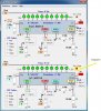
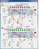
The first 10 LEDs work in dot-mode! Accepts a 0-6VDC signal and turn on or off sequentially from left to right with increased voltage. Thank you so much, eric.
Now, for the rest...
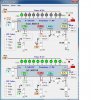
The first 10 LEDs work in dot-mode! Accepts a 0-6VDC signal and turn on or off sequentially from left to right with increased voltage. Thank you so much, eric.
Now, for the rest...

![29062011_001[1].jpg](/data/attachments/46/46557-b49e8f473daa1239b44588497c6794e9.jpg?hash=tJ6PRz2qEj)

![29062011_001[1].jpg](/data/attachments/46/46558-ce0167d01fb366e52aac48d54001384a.jpg?hash=zgFn0B-zZu)
