Continue to Site

Welcome to our site!

Electro Tech is an online community (with over 170,000 members) who enjoy talking about and building electronic circuits, projects and gadgets. To participate you need to register. Registration is free. Click here to register now.

  • Welcome to our site! Electro Tech is an online community (with over 170,000 members) who enjoy talking about and building electronic circuits, projects and gadgets. To participate you need to register. Registration is free. Click here to register now.

So much trouble, so little time...

Status
Not open for further replies.
I was hoping to avoid this.

I've been lurking on this forum for quite a while now, and I've joined a month or two ago. I am a mechanical engineer, but was recently assigned an electronics project since I have shown an interest in these things. Now I'm just getting depressed.

I have to make a fuel level indicator, so I found on this forum that I can do so using a lm3914 chip. I have ordered two of these and a 20LED bar, with several 1M and 10k resistors (10 of each), a few 2.2µF caps, and borrowed a breadboard. (She was kind enough to "forget to mention" the few 470Ω and 4.7kΩ resistors lying around with the breadboard.)

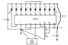
I tested each and every "row" and "column" of the breadboard for contact, mostly because I forgot how a breadboard is wired. I then connected the circuit as per the data sheet, applied a 12Vdc input over the chips, 6V with a 10kΩ pot to simulate the signal (which must ultimately be 0-5Vdc) and watched in awe as nothing happened. The LEDs have a driving voltage of ±3Vdc, which I obtained by dividing the 12Vdc with a 10kΩ and two 4.7kΩ and picking up between the 2 4.7kΩ resistors. I will draw a diagram if necessary, but instead I'm risking getting banned by requesting anyone with a heart to please, please, pretty please give me a complete, clear circuit so I can just bloody order the components and build the fuel level indicator. If there are things I would like to know ("how did you know what size resistors to use?", "where did you get those values from?", "calcs?") I'll ask, but right now I need results pronto.

I've searched using Google and "Search forum" and have read through many lm3914-related posts and threads, but I am not smart enough to decide which thread will help me the best. If you could recommend one of those, it'd be swell!

Apologies in advance. I'm seeking help from an actual electronic engineer, but first I have to find one...
 
OK, before worrying about cascading the LM3914 I would start by using this data sheet and set things up exactly like the very first application example which is set up for 0 to 5 V input. Just make sure that the LED polarity is correct! Getting that first application design to work will take out 80% of the headaches. Since we can't see your circuit this will have to do as a start.

Ron
 
(She was kind enough to "forget to mention" the few 470Ω and 4.7kΩ resistors lying around with the breadboard.)
Are you blaming her for lending you something?

The LEDs have a driving voltage of ±3Vdc, which I obtained by dividing the 12Vdc with a 10kΩ and two 4.7kΩ and picking up between the 2 4.7kΩ resistors
Sounds like the LEDs won't have any current available with such high resistor values. Just to get it up and running, replace the 10kΩ with a 470Ω and dump the 4k7s

I'm seeking help from an actual electronic engineer, but first I have to find one...
Huh?:confused:
 
Last edited:
Are you blaming her for lending you something?
NOT A CHANCE!!! That little oversight is coming in far too handy. I should feel a little guilty for not asking whether she wants them back...

I'm still looking for an actual electronic engineer...


Don't feel too bad - we South Africans are notorious for our cynical sense of humour.


@Reloadron:

I'll see what I can do about drawing my diagram and posting it. I was really hoping not to, since there are already so many threads on lm3914, but if it will help you help me, I'll do it. BTW, somehow the data sheet doesn't download (may be on my side), but if it is anything like the one I've got, then the only problem with the circuit on p2 is the fact that drives only 10 LEDs. Mine was built like the one on p15, without the bar-dot-selection, since I'm only interested in bar. Not because I wanted to look smart, but because our fuel tank has a weird geometry, and the decision was taken to indicate 3/4, 1/2 and 1/4 with stickers. If I can't even do something this simple, imagine me trying to incorporate some logic as well. I relatively sure this part of the circuit is correct, since I used this to order the components.

You know what, I'll draw my diagram. Thanks in any case.
 
So did you try swapping out the resistor as mentioned above? If the circuit is almost as in the datasheet, it should almost work.

Don't let me detract from your doodling though.

EDIT: sorry for my misunderstanding above, I had no idea what you meant.
 
Last edited:
OK, so here is exactly how my circuit is connected to the breadboard. The final product will have to be powered by a 12V DC power supply, which actually may go from 14.4V to 10.5V, or even 9V (car batteries). If this may presnt a problem, I'll address it later, although suggestions are welcome anytime.

Including what's on this circuit, I have the following resistors available: 10 x 1MΩ, 10 x 10kΩ, 1 x 10kΩ rheostat, 4 x 1kΩ, 2 x 470Ω and 2 x 390(?)Ω. I also have used 2 out of 10 x 2.2µF capacitors. What may I need to get for this circuit to work?

I've also attached the data sheet for the 20LED bar, and I assume the LM3914 data sheet is the same as mine.

Thank you all.
 

Attachments

  • Circuit.pdf
    28.6 KB · Views: 223
  • 20 segment LED bar.pdf
    69.7 KB · Views: 149
BTW, Reloadron, my bad, they were 470 Ω, not 4.7kΩ resistors. I actually connected 10 of the LEDs first, but that didn't work either. I may try again, though - I can't imagine another way to check the LMs.
 
Last edited:
How about removing the resistor divider?

Pin 3 is the supply and should be connected to a stable supply rail; e.g. the 12V bus bar would be a good choice. Pin 3 and Pin 9 should be connected directly together for bar mode.

Pin 4 should have a lower impedance source - e.g. GND or the VREF of the other LM3914. The 2x 1M resistor divider is no good, adjust the reference by using resistors on the REFOUT and REFADJ pins.

So have you found any real actual engineers yet? :p
 
On page 2 of the datasheet https://www.electro-tech-online.com/custompdfs/2011/06/LM3914-1.pdf, there's a circuit that will work with an input voltage 0-5V, in bar mode which is basically what you want. Wire up that first. When you have that working, it's very easy to continue to the next step of getting the 2nd lm3914 done.

Circuit attached for single unit. Try building that first.

When you've done that, I'll post the bit for adding the 2nd LM3914.
 

Attachments

  • Clipboard01.png
    Clipboard01.png
    11.1 KB · Views: 143
Last edited:
@ericgibbs

Great link!... what's it do? Support/exlanation docs? It also doesn't seem to work on Win7 x64.

Please treat me like the noob I am. Even though I'm a little pressed for time, I still would like more than a "black box"-solution.

As we say in SA, "buy a donkey".

(If you want to know what the donkey's for...)
 
Hi Eric,
You'll notice the 470 was always stated as a 'temporary' measure, as it would actually allow the circuit to function instead trying to power the IC and LEDs from a high impedance voltage divider.

The REFADJ of the second circuit can be fed from the REFOUT of the first. R1=R2 for a 2.5V span for each, the first from 0-2.5V and the second from 2.5V-5V. Then extra auxilliary resistor can be added to set the current of the 2nd without bothering with any fancy calculations.
 
How about removing the resistor divider?

Pin 3 is the supply and should be connected to a stable supply rail; e.g. the 12V bus bar would be a good choice. Pin 3 and Pin 9 should be connected directly together for bar mode.

Pin 4 should have a lower impedance source - e.g. GND or the VREF of the other LM3914. The 2x 1M resistor divider is no good, adjust the reference by using resistors on the REFOUT and REFADJ pins.

So have you found any real actual engineers yet? :p

Actually, I'm still looking for an actual EE. If they are anything like our electronics lecturers, then I'm gonna grow old searching...

What resistors should I use for... actually, from my inventory, is anything not there that should probably be there?

I'll rebuild the circuit for 10 LEDs ASAP. Of course, I can't skip my actual job to do it - I built this circuit while I was booked off with flu, which probably explains, well, everything...
 
hi,
You have to install as Administrator on Win7, did you download and install the Visual Basic runtime files as stated in the text.
When you getting it working, you will see that the module is intuitive.

I spend a lot of time in SA, in the PE area, never heard the donkey bit.
 
Another stupid question: Why is the voltage divider at Pin 7 and Pin 8 ±3:1 (1.21k:3.83k)? Shouldn't they be equal? Otherwise, why is Pin 6 not connected to my +6V source, which is Ref_Hi after all?

I' guessing the actual circuitry of the LM3914 isn't exactly as described on p7, it just can be thought of in that way? Some calcs would be handy now.
 

Attachments

  • Circuit Try2.pdf
    27.7 KB · Views: 201
Last edited:
This is your circuit with corrections.

What actual voltage range do you want the two LM3914's to cover.?
 

Attachments

  • AAesp04.gif
    AAesp04.gif
    38.3 KB · Views: 145
The fuel level indicator itself will be powered by batteries as explained. Right now I'm using a 6VDC source to see if the circuit will work, but it will ultimately be used with a 0-5V capacitive fuel level sender. All I know is that the capacitive fuel level sender gives a signal from 0-5VDC. If I get the sender itself, I'll be able to tell you more, seeing as the manufacturer is quite economical with info.

Does the fact that I've only got a 6VDC, 9VDC or 12VDC (being used to power the circuit at the moment) affect something big? If so, how and why?

Also, how would the values of the 2 x 1k resistors connected to Pin 7 affect the LEDs? How do I use the LED data sheet to select the correct R?

Why do all electronic system seem to work like magic, or not work at all? If it were gears, or pistons, or spring and linkages...
 
Last edited:
hi,
If you could get that LM3914 simulator to run [ the single version first] you would see in real time what is happening as you tweak the R values.
Did the Administrator install work.?

BTW: with 6V you dont need the 27R

With a 6V supply, the Vinput will only work to 6V -1.5V ie: 4.5V
 
Last edited:
Status
Not open for further replies.

New Articles From Microcontroller Tips

Back
Top