Electro Tech is an online community (with over 170,000 members) who enjoy talking about and building electronic circuits, projects and gadgets. To participate you need to register. Registration is free. Click here to register now.
Welcome to our site! Electro Tech is an online community (with over 170,000 members) who enjoy talking about and building electronic circuits, projects and gadgets. To participate you need to register. Registration is free. Click here to register now.
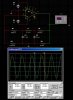
It is fairly simple. We have a 10kHz pulse input. The L and the two C's forms a resonator (pi-filter) at the required frequency, giving 180 deg phase shift (higher order harmonics attenuated after passing through the resonator), and together with another inversion going through the 555 gives a total of 360 degrees. This in-phase feedback together with > 1 (~4) gain through the 555 satisfies the condition for sustained oscillation.
Graph of the Fourier (spectrum) analysis show the harmonic content at the input of the resonator and how only the fundamental remains at the output.
And just to prove that the 555 acts only as a invertor like I previously explained, I replaced the 555 with a logic invertor. The result is the same, oscillation at 10kHz
In fact it does not matter what we use for the invertor, as long as it has enough gain to overcome the losses around the circuit, you will have oscillations. Here on the left, a common emitter amplifier with gain >1 completes the loop, and once again oscillations at 10kHz. Even a JFET will do nicely as shown on the right.
And lastly, Zach one specially for you. Here we even kicked your IRF510 into oscillation. The pot on the gate is set to be near the gate threshold voltage (~2.5 - 3V)
Could you attach the files of those schematics, I'm trying to learn how to use Proteus Pro demo and it would make things seasier for me to browse through the circuit and check how did u configure the values and stuff.
I don't have all of them anymore as I modify old ones into new circuits. If you PM me I could email you the ones I still have. Also I am not sure that all will run on the demo version cause of the models.
I hate to burst this bubble, but to state that we can get a sine wave out of a 555 is not really true even though we see what looks like a sine wave on the 'scope'. That's because it is not coming directly out of a the 555, it's coming out of the LC network. There is never a doubt that we can get a sine wave out of an LC network with the right values chosen, but there's still no way it is coming from the 555 itself.
Just to note, almost any wave shape that is fed into a filter like a bandpass filter will produce a sine wave. That includes a square wave, triangle wave, rectangular pulse, etc.
There also appear to be what looks like a redundant resistor in there.
The OP (TheOne) never said that the sine wave was from the 555 output. In fact, he explicitly stated that it was not.
BTW, I wonder if TheOne has died. His last post was in October of 2007.
This site uses cookies to help personalise content, tailor your experience and to keep you logged in if you register.
By continuing to use this site, you are consenting to our use of cookies.

")