Continue to Site

Welcome to our site!

Electro Tech is an online community (with over 170,000 members) who enjoy talking about and building electronic circuits, projects and gadgets. To participate you need to register. Registration is free. Click here to register now.

  • Welcome to our site! Electro Tech is an online community (with over 170,000 members) who enjoy talking about and building electronic circuits, projects and gadgets. To participate you need to register. Registration is free. Click here to register now.

Simple Relay Timer

Status
Not open for further replies.

CPM169

New Member
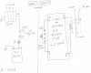
Hi everyone, this is my first post here. I'm a novice and would like help with this circuit (see JPG file below). I need a N/O push-button to activate a relay for less than one hour. This relay would switch power between a solar cell and a 9-V battery.

I'm guessing that the solution would be to drain a capacitor at a slow rate through the relay coil.

I would like to use the existing 9-V battery to run this new circuit if possible.

This is a present for my daughter and I don't want the battery to die too soon because she will forget to switch it back to solar power at one point I'm sure.

Thanks in advance for you time helping me!
 

Attachments

  • 9Vtimer.jpg
    9Vtimer.jpg
    235.5 KB · Views: 261
I don't want the battery to die too soon
In that case it would be better to do the switching with transistors instead of a relay. A relay coil drains much more current from the battery than transistors would.
 
Thanks! The relay was just my first idea. If I were to do the switching with transistors, what would that circuit look like?

I have also been toying with the idea of using a 555 timer but I'm really not that familiar with it. Any suggestions on that?
 
The attached circuit should do the trick. R1 and C1 set the time for which the battery powers the load. After the timed period the load is powered by the solar cell instead. When the battery is not powering the load its current is virtually zero, so the circuit needs no 'off' switch. With C=10uF and R1 = 68k the timed period is ~ 1hr. You can reduce the timed period by factors of two by connecting the 'Qselect' line to Q13 or Q12 or......instead of Q14.

Edit: If you're not familiar with the ICs used in the circuit, note that both are CMOS types which require anti-static precautions to prevent damage. The CD4093B IC contains four NAND gates, only two of which are used here. The input pins of the two unused gates should be connected to ground.
 

Attachments

  • BatterySolarSwitch.png
    BatterySolarSwitch.png
    34.1 KB · Views: 241
Last edited:
Thank you very much for this help! This is great!

Now that I understand what a ripple counter is, how about if we make Q14 last for 24 hours. That would make Q8 last for 90 minutes and I would be able to have more time options. What would R1 and C1 have to be? It there an algorithm for finding them?
 
Last edited:
The time constant R1*C1 for the components as shown is 68*10 = 680mS. Just multiply that by the number of hours you want for the switching time at Q14. So for 24hrs multiply 680mS by 24. To achieve that you can increase R1 and/or C1. So, for example, make R1 = 68k*4.8 = 330k (nearest preferred value) and make C1 = 47uF.
Bear in mind that electrolytic capacitors (not ideal for timing) age and have a wide capacitance tolerance, so you will have to experiment with the R1 value if you want a reasonably accurate time. Rather than get 24hrs this way it would be preferable to use a counter with more stages (21-stage available) or to cascade 2 counters, so that a non-electrolytic cap could be used for C1.
BTW if Q14 = 24hrs then Q10 (not Q8) = 1.5 hrs.
 
Fantastic! So here's what I've come up with: To make nice round numbers I've decided to make Q14 16 hours (230kΩ R1 and 47 µF non-electrolytic C1). Then I'd have a choice of 16, 8, 4, 2, 1, 0.5, 0.25 etc. hours.

Also, just to clarify, R5 is not actually a resistor is it? I'm assuming that it represents the load itself since I don't have a resistor after the solar panel. The solar panel connects to a cap, a diode, and a PN2907 transistor.
 
R5 is representative and can be a resistor or your cap/diode/PN2907 or whatever load you like (within reason!). I chose 1k just for the simulation. If the load is inductive then you would need a reverse-biased diode in parallel to suppress any back-emf voltage spikes. Use a pot for R1 (or a pot + fixed resistor), so that the time can be adjusted to allow for C1 variance. I doubt you'll find an affordable 47uF non-electrolytic cap! Good luck with the build.
 
Using a 4040 allows you to remove nearly all the clock components as it has internal clock components.
 
In my Jameco catalog (#112), there is a "Resin Dipped Solid Tantalum 47uF Capacitor" (+- 10%) for $1.25. Product number TAP476K010SCS. Jameco part number 546100. Is that still considered an electrolytic cap?

Also, I like the idea of R1 having a pot.

After looking at the CD4093B data sheet, I see that I will only need one physical chip, and that I will hook up only two NAND gates to it. Do I need to connect anything to the Vdd or Vss pins? I understand also to ground the inputs of the other two nand gates.

The project I'm building is the BEAM Magbot Pendulum found in the "Junkbots, Bugbots, and Bots on Wheels" book and I think that you could consider the load being "inductive" since I'm using a "Major Henry" coil from Solarbotics.
 
Last edited:
I think Colin55 meant the CD4060, not the CD4040 (which is only a 12-stage counter). The problem with the built-in clock of the 4060 is that a non-polarised cap must be used (or two caps back-to-back in series). The 4060 clock circuit is really meant for much higher clock rates than we are using here.
If you do away with the 4093 you would need to replace it with some means of inverting a signal (e.g. another transistor and pair of resistors) for switching from battery to solar power.
'RBLL' refers to low leakage caps. A tantalum cap meets the bill.
Is that still considered an electrolytic cap?
Yes, but it's better than an aluminium type.
Do I need to connect anything to the Vdd or Vss pins?
Yes. +9V to Vdd of the 4093, 0V to Vss. And of course the counter chip Vdd and Vss pins should be connected similarly.
 
Last edited:
Alec_t, you have been a wonderful guide through this learning experience and I do appreciate your time helping me. I'm just about to order the chips. Just a few more questions and I'll let you take a break for a while. 1) What kind of program did you use to make that nice schematic of the switch I'm building? 2) When you say that Vss is 0V, that means it goes to ground right? 3) One final assumption: I can use my 9V battery to power both chips AND power the device as well.
 
Glad to have helped.
1) I used LTSpice, a free download circuit simulator. I recommend it.
2) Yes; Vss = 0V = ground.
3) Yes. The circuit excluding the load only draws about 0.4mA when the timer is running, so the 9V battery can easily power both.
 
Great! I downloaded LTspiceIV and it is really nice. I haven't found the symbol for the trimpot yet. :)

Here is the file for "our" project. I was a little unclear from your picture about the reset pin on the 4020. Let me know if I got it right.

Please forgive my lack of organization but I think it's not bad for a first try.

This is fun!!
 

Attachments

  • BEAM Magbot Pendulum.asc
    6.5 KB · Views: 154
Excellent for a first try. You must be a quick learner with LTS! I'm a fairly recent convert and still learning. It has its quirks, and the 'help' could be more helpful, but hey....it's free, so we shouldn't complain! Where did you find the nice 4020 and 4093 symbols? I was using ones downloaded from the Yahoo LTS-users group.
I haven't found the trimpot yet either, in the LTS files, but a potentiometer model is available from the Yahoo group.
Yes, you've got the reset spot on.
A couple of things though:-
(a) For the 4093 the unused input pins (8,9,12,13) should be grounded and the output pins (10,11) shouldn't.
(b) I haven't analysed the pendulum circuit in detail, and at a quick glance can't grasp what its intended operation is. Should Q2 be an NPN and the 'other way up'?
 
Last edited:
Oh, ya. Inputs. DUH! :eek:

I guess I haven't used logic in a while.

I'm at work right now but when I get home I'll let you know exactly where I got the IC symbols. They were somewhere in one of the "Components" folders. I used datasheets for each of them to determine what each pin did. Then I just threw a lable on them.

As for the pendulum, each of the transistors activate each other very quickly. When the magnet passes over the one side of the coil it is initially drawn toward the center and then the current shuts off. Then as the magnet's momentum moves it off the coil, it induces a current in the opposite direction and lights the LED. Then as the pendulum swings back, the whole thing is repeated.

The coil is a "Major Henry" and you can see one at the Solarbotics website. (solarbotics.com) It is very flat and has very fine wires for maximum number of turns.

I'll be ording the components this evening!

CPM
 
Ok, the 4020 and 4093 symbols are in the "LTspiceIV\lib\sym\Misc" folder. They are named DIP16 and DIP14 respectively.

The order is in! I also added a 10-position rotary switch so I can play with the different timings.

Next week-> soldering!
 
Last edited:
One more small thing. If you look waaaaaay back at the very first picture I submitted (the one that is hand-drawn) you will notice that there is a 10kΩ resister in series with the 9V battery. Where should I put that in the new schematic? I am guessing it will go between the two collectors of the two transistors. On your drawing, that would be between Q1 and Q2.

Or, did you already take that into consideration when you made your schematic?
 
The 10k should, as you say, be connected between the collectors of Q1 and Q2 in my schematic. I overlooked that in my sim.
Ah, so you labelled the DIP16 and DIP14 symbols. Thanks for the info.
 
Status
Not open for further replies.

Latest threads

New Articles From Microcontroller Tips

Back
Top