Continue to Site

Welcome to our site!

Electro Tech is an online community (with over 170,000 members) who enjoy talking about and building electronic circuits, projects and gadgets. To participate you need to register. Registration is free. Click here to register now.

  • Welcome to our site! Electro Tech is an online community (with over 170,000 members) who enjoy talking about and building electronic circuits, projects and gadgets. To participate you need to register. Registration is free. Click here to register now.

Simple logic switch with pushbutton?

Status
Not open for further replies.
ljcox said:
You need a configuration that does not include the B - E voltage drops.

I suggest :-
connect the emitter of the PNP to +3.3 V and the emitter of the NPN to gnd.

Now connect a resistor from the base of the PNP to the logic output and a resistor from the base of the NPN to the same point. Connect the 2 collectors together. In this configuration, the only voltage drop will be the saturation voltage which ought to be about 0.2 V is you have enough base current. Note that the circuit will act as an inverter. So you'll have to account for this somewhere.

Sounds good. I'll draw up a diagram and post it to make sure I havent done anything daft.

The inverter aspect wont be a problem- I can fix that easily with the binary counter, and with a pic10fxxx it isnt even a problem.

If I get it working,I can build an array of them to buffer my programmer for that eeprom programmer I mentioned as well.

Thanks again.

-DAlmation

I'll try it later and post back- thanks.
 
How fast does it need to be?

If it is fairly fast, you will need speed up capacitors across the base resistors.
 
ljcox said:
You need a configuration that does not include the B - E voltage drops.

I suggest :-
connect the emitter of the PNP to +3.3 V and the emitter of the NPN to gnd.

Now connect a resistor from the base of the PNP to the logic output and a resistor from the base of the NPN to the same point. Connect the 2 collectors together. In this configuration, the only voltage drop will be the saturation voltage which ought to be about 0.2 V is you have enough base current. Note that the circuit will act as an inverter. So you'll have to account for this somewhere.


I got this working- thanks!!

Slight problem, though. I'm experimenting with resistor values...

If i make both resistors 100:eek:hm: - transistors nearly burn out.
When I use 1k:eek:hm: for both resistors, it works, but when I input LOW (output high), it is a bit unsteady.

Should both resistors be the same value?

What values would you recommend (3.3V supply).
I'm using ZTX550 and ZTX650, in case it matters. and my inputs are gonna come from a pic microcontroller output pin.

Thanks again- I really, really appreciate it!!

-Dalmation.
Switch2.PNG
 
Last edited:
Okay- I now have this ALMOST working.

I need to use this circuit twice in a bigger circuit (to drive 2 address lines).

When I use two 4.7K resistors, it works great on one address line, but the other is having problems.

It pulls to LOW without problems, but doesnt pull to HIGH quite enough. It needs a few milliamps more.

Is there a way to tweak this circuit to dive slightly harder to vcc?

I'm going mad experimenting here- cant figure out how to fix this.

-Thanks again.

-DAlmation.
 
You should do it by calculation, not by experiment.

In order to ensure that a transistor is saturated, the base current needs to be about one tenth of the collector current.

For example, if you want the PNP transistor to source say 16 mA, then the base resistor needs to be

(3.3 - 0.7)/1.6 = 1.625 k

So use a 1.5 k

Note that I have not allowed for the PIC output voltage.

If it is say 0.1 volt at 1.6 mA, then the calculation would be

(3.3 - 0.7- 0.1)/1.6 = 1.563 k

So again, use 1.5 k
 
Last edited:
Thanks, mate.
I'll try the 1.5K, - it does seem a better base current value.

I'll post back how I get on.

-Thanks again.

-Dalmation.
 
Last edited:
If i make both resistors 100 - transistors nearly burn out.
Make sure that the IO port on the PIC is configured as an output ASAP after reset. When the input to this transistor circuit is floating, BOTH transistors are turned on at the same time and a high collector current will flow possibly damaging the transistors. When the PIC is in reset, all IOs are in the high impedance state (floating) so keep the time between reset and setting TRISGPIO to 0 as short as possible.
 
kchriste said:
Make sure that the IO port on the PIC is configured as an output ASAP after reset. When the input to this transistor circuit is floating, BOTH transistors are turned on at the same time and a high collector current will flow possibly damaging the transistors. When the PIC is in reset, all IOs are in the high impedance state (floating) so keep the time between reset and setting TRISGPIO to 0 as short as possible.
This is a good point.

You could reduce the dissipation by connecting resistors (say 2R7) in series with the collectors. These would limit the current while the i/o is in the hi Z mode.
 
would a 10K pull down resistor connected to the base of the PNP and ground prevent it opening on high z input, without affecting normal operation too much?
 
dalmation said:
would a 10K pull down resistor connected to the base of the PNP and ground prevent it opening on high z input, without affecting normal operation too much?
That was my first thought.

But 10k will make virtually no difference.

What you're trying to do is to shunt the current from the base of the PNP to gnd so that the NPN won't turn on.

I estimate that with two 1.5 k resistors connected to the bases, the base currents will be about 667 uA.

A 10 k resistor would only shunt about 160 uA, so the rest (ie. about 500 uA) will go into the NPN. This is more than adequate to turn it on.
 
You could also change the PIC to one with 2 more pins and drive each transistor separately. Just be very careful when you write the code. ;)
Here are a couple more solutions for you. The one with the extra transistors is the more elegant one:
 

Attachments

  • switch2.PNG
    switch2.PNG
    10.3 KB · Views: 165
  • switch.png
    switch.png
    9.8 KB · Views: 142
Last edited:
dalmation said:
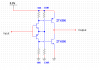
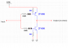
Is this what you mean?

Will that not limit my output push/pull current?

View attachment 15068
Yes & yes.

However, limiting the output current is not the critical issue.

The critical issues are the output voltage and the switching speed. The latter can be improved (if necessary) by placing capacitors (of the right value) across the 1k5 resistors.

You stated in an earlier post that the output current is :gtoet: 50mA.

At 50 mA, the voltage drop across a 2R7 resistor will be about 0.135 Volt.

We must also consider the transistor saturation voltage. So, for the sake of argument, assume it is 0.1 V. Thus the voltage drop will be about 0.235 V. (you need to choose transistors designed to operate as saturated switches with minimal saturation voltage @ 50 mA and with minimal storage delay)

So, the question is - is this acceptable to the IC that is being driven? If not, you can reduce the resistors a little, but that will increase the short circuit current. So you have to determine whether the transistors can withstand that level of current for the time it takes the PIC to initialise.

The 2 circuits posted by kchriste are good ideas, but I'm not sure whether they will be fast enough for your purpose since the transistor storage delays may be excessive.

How fast does it need to be?
 
Last edited:
thanks for all that-

The switching speed for this application is extremely slow (very, very maximum would be about 10Hz, but normal operation about 0.1Hz) so no probs there.
 
You're welcome.

Another possible issue is the rise and fall times of the waveform. I suggest you study the data sheet of whatever IC the transistors are driving to see what the limits are (if any)
 
Status
Not open for further replies.

Latest threads

New Articles From Microcontroller Tips

Back
Top