Continue to Site
Follow along with the video below to see how to install our site as a web app on your home screen.
Note: This feature may not be available in some browsers.

The reverse current is slightly less than the forward current (19.9mA instead of 20.0mA). But since the reverse voltage is much higher then the heating is much higher.Well, how much reverse current are we talking about here; microamperes? Not much, at any rate, I'll wager.
I didn't want to pay to read the whole article but the implication is clear.
So the real question is where does the led suck up the light from when it is reversed biased. Just a really small spot like a black hole or just a little bit from the whole room?
Without quantifying this, we're just taking shots in the dark.
I think my initial guess was at least in the ballpark; I just checked a datasheet for some LEDs I have (medium-high-intensity red), and it gives a Vr of 5V (minimum, typ. = 20V) at an Ir of 100µA. So really not very much. I suspect this is not being exceeded, or at least not very much, by my line-powered LED over in that other thread.
"Ir of 100µA. So really not very much" The data sheet might say 100uA (at 5V) but the current has to be 20mA (at 8v) or whatever the forward current is. You can't pass DC through a capacitor. The forward and reverse current must equal.
Reverse breakdown is not a little leakage current. It is when the junction has avalanche breakdown like a zener diode with only the capacitor's reactance limiting the current.Perhaps, but the $64,000 question is, how much? Without quantifying this, we're just taking shots in the dark. Again, what sorts of leakage currents are we talking about here?
I think my initial guess was at least in the ballpark; I just checked a datasheet for some LEDs I have (medium-high-intensity red), and it gives a Vr of 5V (minimum, typ. = 20V) at an Ir of 100µA. So really not very much. I suspect this is not being exceeded, or at least not very much, by my line-powered LED over in that other thread.
I just checked a datasheet for some LEDs I have (medium-high-intensity red), and it gives a Vr of 5V (minimum, typ. = 20V) at an Ir of 100µA.
Huh? Why must the forward and reverse current equal? It's a diode. Since when do the forward and reverse currents equal, say in a typical power supply diode?
The reverse diode doesn't need to be a high-voltage type such as the 1N4007. The maximum reverse voltage this diode experiences is the forward voltage of the LED (<5V). Using a second LED as the reverse diode is the preferred option, as the combination gives light on both half-cycles of the mains.put a reverse diode across the LED to prevent reverse breakdown of the junction of the LED. use a 1N4007 for this
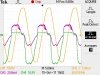
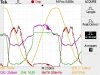
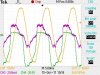
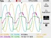
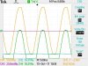
I have a bag full of hundreds of surplus LEDs from years ago, so I decided to make some measurements. Using a Tektronix TPS2042 scope with 4 isolated channels and a clamp-on DC responding current probe, I captured some scope images.
I connected a .47 µF X2 capacitor in series with the LED and connected it to the grid. I tried this several times and each time the LED worked right away; I didn't have any initial failures to illuminate. I disconnected and reconnected the arrangement to the grid numerous times and with any given LED, after several re-connects, the LED would fail, usually shorted.
In these images, the grid voltage is shown in orange, the LED (and capacitor) current in purple and the voltage across the LED in green. ... [snip]
YesDuring positive half-cycles, the capacitor will charge as shown on the left, correct?
No!But on negative half-cycles, doesn't the stored charge counteract the line voltage, as shown on the right? Doesn't this lessen the reverse voltage across the LED?
The fact that the LED lights means that current is flowing into the capacitor every cycle, which means that current is flowing out of the capacitor every cycle as well.