Continue to Site

Welcome to our site!

Electro Tech is an online community (with over 170,000 members) who enjoy talking about and building electronic circuits, projects and gadgets. To participate you need to register. Registration is free. Click here to register now.

  • Welcome to our site! Electro Tech is an online community (with over 170,000 members) who enjoy talking about and building electronic circuits, projects and gadgets. To participate you need to register. Registration is free. Click here to register now.

Simple AC Powered LED

Status
Not open for further replies.
That youtube video is amazing.
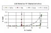
He measures -5.35 volts DC across the LED. I could not see if the LED was red or white. If white the forward voltage will be about 3 volts (50% of the time). If the meter is reading -5.35 then the LED must have 8.35 volts (for the other 50% of the time). -5.35=average(+3, -8.35) It looks like the LED current was really low. That's good for the LED in this case.
The LED was built for 3V and 20mA at 100% or 60mW.
LED power = (3V, 20mA 50%=30mW)+(8.35V, 20mA 50%=83.5mw)=113.5mW That's 2x the power and 1/2 the light as rated. Light for 50% of the time.

As mentioned most people have a discharge resistor across the cap. (AND) Usually there is a resistor in series with the cap to limit the high frequency energy going through the LED. The cap at 60hz limits the current. There can be high frequency noise from computers, monitors, microwave ovens and lightning strikes that could rip through the cap with out much limiting.
 
If its only 1 or 2 volts forwared voltage across the LED with the cap, would it not be about the same reverse voltage?
 
As mentioned most people have a discharge resistor across the cap. (AND) Usually there is a resistor in series with the cap to limit the high frequency energy going through the LED. The cap at 60hz limits the current. There can be high frequency noise from computers, monitors, microwave ovens and lightning strikes that could rip through the cap with out much limiting.

This has been mentioned before in discussions on this subject. But it seems like a needless worry.

Think about it: sure, there is going to be such noise on a power line. But what's the magnitude of that noise? My guess is that it can probably be measured in millivolts for the most part. Certainly not enough to cause damage to a LED, after being attenuated somewhat by the capacitor.

The thing that would kill the LED would be a large spike, like from an industrial motor controller or some such. Not much danger from TVs, computers, other things with SMPSs. At worst, there might be some high-frequency ripple on the line.
 
Last edited:
If its only 1 or 2 volts forwared voltage across the LED with the cap, would it not be about the same reverse voltage?
The forward voltage of an LED depends on its color:
infrared= about 1.2V.
red= 1.7V to 2.2V.
yellow or old green= about 2.2V.
blue, new green or white= 3.2V to 4.5V.

When one LED is used then it lights half the time and breaks down half the time. The measured voltage is the average of both.
Most ordinary LEDs have a max allowed reverse voltage of 5V but some are 1V and others are 10V. The actual reverse breakdown voltage is not listed because it should never be activated. Use two identical LEDs back-to-back then they are not damaged, they flicker much less and produce double the amount of light.
 
...The thing that would kill the LED would be a large spike....
The resistor in series reduces the huge current spike when the power is first turned on maybe at the peak voltage of the mains (170V or 340V) and the discharged capacitor charges through the LED with nothing except the resistor limiting the current.
 
Ok with the cap limiting current and voltage and the reverse voltage limit higher than the forward voltage of the LED, than it should be fine right?
 
None of the following makes any sense:
Ok with the cap limiting current and voltage and the reverse voltage limit higher than the forward voltage of the LED, than it should be fine right?

1. The cap does not limit the voltage.
2. "the reverse voltage limit higher than the forward voltage " This makes no sense.
3. "than it should be fine right?" The English word should be: "then" Almost no-one understands the difference between: "then" and "than."
 
None of the following makes any sense:


1. The cap does not limit the voltage.
2. "the reverse voltage limit higher than the forward voltage " This makes no sense.
3. "than it should be fine right?" The English word should be: "then" Almost no-one understands the difference between: "then" and "than."

If the cap is not limiting the voltage then what is?
The LEDs forward voltage is about 1 to 2 volts. The LEDs Max reverse voltage limit is 5 volts. Witch is higher?
The "than" was a typo.
 
If the cap is not limiting the voltage then what is?
The LEDs forward voltage is about 1 to 2 volts. The LEDs Max reverse voltage limit is 5 volts. Witch is higher?
The "than" was a typo.

Nothing is really limiting the voltage. That is the problem.
I believe he was saying that the fact that the reverse voltage is higher than the forward voltage does not significantly affect "what is okay" or not.
 
Last edited:
The LED is not simply a piece of very hot incandescent wire, it is a diode.
Its forward voltage rating limits its forward voltage and its reverse breakdown limits its reverse voltage like a zener diode.
So an LED limits its own voltage. If you don't limit its current with something then it burns up.

The capacitor limits the "average" current but you still need a resistor in series to limit the very high peak current that will occur if the power is turned on at the moment when the AC voltage is at its peak voltage.
 
Hi delphijustin,

you might consider using that little circuit for safe LED operation.

Output voltage depends on C1 capacitance and D3/D4 value.

Note that the zener diodes are used like normal diodes.

Boncuk
 

Attachments

  • LED-MAINS.gif
    LED-MAINS.gif
    13.7 KB · Views: 163
The reverse zener voltage can vary quite a bit from lot to lot of LED diodes. Get a batch with high zener breakdown of 10-12 volts and the power dissipation during reverse current times the higher zener voltage may blowout the LED. All the diodes tested for actual reverse breakdown in the graph had 5v breakdown voltage specs, which is a common 'boiler plate' spec for LED's.

If you happen to 'bounce' the connection as it is plugged in, you can charge the cap, miss the discharge cycle, and reconnect at peak of AC input such that it doubles the initial surge current on the LED, again risking its destruction.

Back to back LED's means two LED's in parallel with reverse polarity connection. Each conducts on alternate half cycles balancing the forward and reverse current through series capacitor.
 

Attachments

  • led_reverse breakdown voltage.jpg
    led_reverse breakdown voltage.jpg
    43 KB · Views: 245
Last edited:
Hi delphijustin,

you might consider using that little circuit for safe LED operation.

Output voltage depends on C1 capacitance and D3/D4 value.

Note that the zener diodes are used like normal diodes.

Boncuk

I have seen many circuits with Zener diodes. I don't understand why. A LED is much like a Zener! I can't see why we need a Zener across a LED.
I often see 1n4007, 6, 5, 4 used when there is only 4 volts across the diodes.
 
Are there any electrical engineers here that for sure know they are talking about? I would like to know why and how this works without guesses and opinions.


Moderator: clean up the language
 
Last edited by a moderator:
I have seen many circuits with Zener diodes. I don't understand why. A LED is much like a Zener! I can't see why we need a Zener across a LED.
I often see 1n4007, 6, 5, 4 used when there is only 4 volts across the diodes.


The purpose of the zener is to take the possible surge, particularly during a bounce connection where series cap get a double charge. A shunt capacitor also helps by damping out the startup transient surge.
 
Are there any electrical engineers here that for sure know they are talking about? I would like to know why and how this works without guesses and opinions.

There are several members here who know what they are talking about, and have explained it well. The point is that it may work for some LEDs, but only by pure luck. It is by no means a safe or efficient way to drive an LED, and people have gone over this several times.

Der Strom
 
Last edited by a moderator:
It is by no means a safe or efficient way to drive an LED, and people have gone over this several times.

You're definitely wrong on the second count ("or efficient"), and I challenge you on that point.

It's certainly more efficient to use the reactance of a capacitor to limit the voltage and current to the LED than using a resistor.

Do the math with my little circuit and you'll see how little power (essentially zero) is dissipated in the capacitor.

To be honest, I would actually say it's less efficient than it is safe. You're running a small device that only needs between 1.5 and 3 volts to operate and draws ~25mA on average on mains power. Regular LED drivers are made to be very efficient, waste very little power, and are much, MUCH more reliable. The setup with the cap and a single LED wastes a more power than a traditional LED driver would, hence it is much less efficient. Perhaps you need to look up the definition of the word. Speaking of which, I'm not convinced you really even know what you are doing. There are lots of experts here who have done this sort of thing all their life, yet you just brush off their accurate and thorough explanations like they are worth nothing. You're stuck with your own stubbornness. You think that just because it works with a few LEDs means it is an okay way to drive one, and I assure you that it is not. It most certainly is not reliable (as you yourself admitted--you blew several LEDs by trying this method). Nobody is saying it can't work. We already know that it is possible. The argument is that it shouldn't be used as a common way to drive an LED. There are much better, safer, and more efficient methods out there that should be used instead. Get over yourself. Think about what other people are saying--and I mean actually think about it. You might learn something that you don't know yet.

I do not intend this to be rude. I simply want you to understand and actually consider what other people are saying. Otherwise, I don't see how this thread can proceed any further. It will become nothing more than a bunch of guys arguing about a simple circuit. Personally, I'd like to see something come of this thread. I've even learned from it myself. I just want you to do the same.

Regards,
Der Strom
 
Last edited:
Well, you've done nothing to prove that this is a less efficient way to drive a LED from an AC power line than some other way. I'd go so far as to say that it's probably more efficient than using any kind of "LED driver" (meaning some sort of converter, like a buck converter), since all those have some losses (small, but not zero).

Notice I didn't say "safer", or even "better". The current topic is efficiency.

I'm always ready to be convinced otherwise, but I'd need some proof. Claiming that one should do things "by the book" is not a convincing argument, in and of itself.

Don't worry; I take no offense at your comments. You do seem, though, to be taking quite an orthodox approach here, with not much supporting evidence.
 
Last edited:
The wasted power that reduces efficiency in the simple circuit with a capacitor driving the LED is when the LED is in breakdown half the time with a reverse current that does nothing except heat the LED. Also, the breakdown voltage has no maximum so its voltage might be high enough to over-heat the LED.
 
Status
Not open for further replies.

Latest threads

New Articles From Microcontroller Tips

Back
Top