Thought and Memory
New Member
Hello. First post as I am needing some advice.
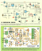
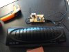
My old and faithful modded laminator died recently. It used an household iron thermostat to control the temperature and worked very well for the toner transfer method of PCB fabrication and creating sheet metal decorative items using the toner and etch method.. But having got a new unit to modify I decided to use a digital circuit to control the heater elements. After some browsing I came across this unit in the Silicon Chip magazine Jan 2007.
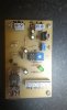
I made the PCB myself and have built it. The fun started when testing. To set the unit to a given threshold you measure the voltage at the wiper of VR1. This equates to a given temperature (though testing the actual temp will be done to ensure accuracy). It can be set to sense High to low or Low to high and has adjustable hysteresis.
Set up as is in the diagrams it seemed to be working backwards. Though I may be confused. So the set up and use of his circuit will be...
Using the normally closed relay contacts to switch the heater elements on and off. The thermistor will be fitted to the aluminium extrusion, where the heaters, are located to detect the temp of course. Temp setting to affect transfer of the toner will be 170° - 180°. So initial state when powering up Laminator and the thermostat circuit. Heaters live. Relay not activated. When temperature reached Heaters off, Relay activated.
My problem is as set up it initially wouldn't trip the relay. The LED indicator was on at power up so the relay should have tripped. Initial test state of pots was full anti clockwise on hysteresis and turn set point to full anti clockwise until the LED and relay activated as per the article text. This would be 0°. Initial state in H/L was relay activated (once fixed). So at this point the initial state was power on relay activated. Not what I wanted.
I solved the relay not tripping by changing the indicated resistor to 1K. I should point out I used a BC558 as I had one to hand and not the specified BC337. Is this why it wouldn't work initially?
To get the correct initial state of relay in the NC and switching at higher temperature I had to change link1 to the H/L setting and reverse the diode D3 as described in the text. So it works, subject to calibration and fitting to the laminator. But I would like a second opinion on the accuracy of my correction and understanding of the H/L - L/H setting.
I am just a hobbyist with electronics. I know enough to be dangerous but successful enough with most projects and fault finding where I can.
Thanks in advance
T&M
My old and faithful modded laminator died recently. It used an household iron thermostat to control the temperature and worked very well for the toner transfer method of PCB fabrication and creating sheet metal decorative items using the toner and etch method.. But having got a new unit to modify I decided to use a digital circuit to control the heater elements. After some browsing I came across this unit in the Silicon Chip magazine Jan 2007.
I made the PCB myself and have built it. The fun started when testing. To set the unit to a given threshold you measure the voltage at the wiper of VR1. This equates to a given temperature (though testing the actual temp will be done to ensure accuracy). It can be set to sense High to low or Low to high and has adjustable hysteresis.
Set up as is in the diagrams it seemed to be working backwards. Though I may be confused. So the set up and use of his circuit will be...
Using the normally closed relay contacts to switch the heater elements on and off. The thermistor will be fitted to the aluminium extrusion, where the heaters, are located to detect the temp of course. Temp setting to affect transfer of the toner will be 170° - 180°. So initial state when powering up Laminator and the thermostat circuit. Heaters live. Relay not activated. When temperature reached Heaters off, Relay activated.
My problem is as set up it initially wouldn't trip the relay. The LED indicator was on at power up so the relay should have tripped. Initial test state of pots was full anti clockwise on hysteresis and turn set point to full anti clockwise until the LED and relay activated as per the article text. This would be 0°. Initial state in H/L was relay activated (once fixed). So at this point the initial state was power on relay activated. Not what I wanted.
I solved the relay not tripping by changing the indicated resistor to 1K. I should point out I used a BC558 as I had one to hand and not the specified BC337. Is this why it wouldn't work initially?
To get the correct initial state of relay in the NC and switching at higher temperature I had to change link1 to the H/L setting and reverse the diode D3 as described in the text. So it works, subject to calibration and fitting to the laminator. But I would like a second opinion on the accuracy of my correction and understanding of the H/L - L/H setting.
I am just a hobbyist with electronics. I know enough to be dangerous but successful enough with most projects and fault finding where I can.
Thanks in advance
T&M