Just like to point out, we posted at the 'same' time, I didn't ignore this post

However, AG has gone through it even more than I was planning, and done it in one go - I was doing it a bit at a time - although he hasn't approached the lack of stage decoupling.
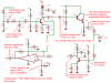
From the style of your disgram, would I be correct in assuming you're 'designing' using a simulator? - if so I presume you're just sticking bits of circuits together and changing values until you get something out?.

")