Continue to Site

Welcome to our site!

Electro Tech is an online community (with over 170,000 members) who enjoy talking about and building electronic circuits, projects and gadgets. To participate you need to register. Registration is free. Click here to register now.

  • Welcome to our site! Electro Tech is an online community (with over 170,000 members) who enjoy talking about and building electronic circuits, projects and gadgets. To participate you need to register. Registration is free. Click here to register now.

sensors etc.

Status
Not open for further replies.

PG1995

Active Member
Hi

I'm trying to make a voltage sensor which can be used to sense voltage of 12V solar panel. The output of the sensor will be connected to the analog-to-digital input of a PIC microcontroller whose maximum input voltage cannot exceed 5V.

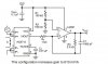
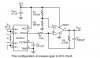
This is the setup I intend to use. The voltage of 12V panel could typically touch 18V so I think we should use this figure to calculate the values for resistors R9 and R10. Note that op-amps are being in inverting configuration and gain is given by -Rf/Ri. I believe the values should be such that (R9/R10)=0.28 because 18*0.28=5. Do I have it correct?

The second op-amp, i.e. U2, can be used to make the output of first op-amp positive and values for R8 and R11 could be chosen to get unity gain. Do I have it right?

Is the value, 1 nF, for input capacitor C2 okay if PWM frequency is going to be around 30 kHz and sampling frequency is around 6.5 kHz?

Thank you for the help.

Regards
PG
 

Attachments

  • voltage_sensor1.jpg
    voltage_sensor1.jpg
    88 KB · Views: 1,776
The impedance on the PIC ADC should not get above 10k.
So; R2=10k.
C1= something so the switching noise does not get to the ADC.
R1, so that there is a 4:1 divide by.
The ADC input has clamping diodes so the pin will self limit to -0.7 and 5.7 volts. As long as the current is low that is fine.
upload_2014-5-30_14-19-24.png
 
Thank you, ronsimpson.

But why is what I suggested in my previous message wrong? What problems does it it have? Thanks.

In this datasheet for a current sensor on page #2, it says that sensitivity is 185 mV/A. What does it really mean? Does it mean that for every one ampere change in input current, there is a change of 185 mV? Please note that the value 185 mV/A is for a (+/-)5A current sensor, then assuming what I'm saying is correct, it would mean that for 5A input current, the output voltage would be 925 mV. Do I have it right? Thanks.

Regards
PG
 
Last edited:
You only need to scale the voltage down. so the simple voltage divider network will work fine.
You would only need opamps if you needed to scale the voltage up.
 
I'm trying to make a voltage sensor which can be used to sense voltage of 12V solar panel.
Now you want current?

The ACS712 outputs approx. +/- one volt. (where 0=1/2 VCC)
Current of +/-5A makes +/-0.925 volts.
0.925V/5A=0.185V/A

-5A in= 2.5V-0.925=1.575
0A in = 2.5V-0=2.5
+5A in = 2.5V+0.925=3.425
 
Thank you, 4pyros, ronsimpson.

This is my humble request that please try to keep your answers to the point and as clear as possible because I need to be done with these sensor related questions today. Thanks for the understanding and help.

Voltage Sensor:
Yes, 10k is the maximum recommended source impedance but the acquisition time can be reduced by reducing the size of source impedance. For instance, this reference gives that maximum acquisition time is 19.72 us when Rs is 10 kOhm (page #428) and minimum acquisition time is 10.61 us when Rs is at its allowed minimum value that is 50 ohm (page #429). So, why not use a voltage follower like this to reduce the acquisition time? Is this okay?

(This is a note to self.)

I don't think I need to use a bipolar supply for the op-amp because I'm not going to detect negative voltage therefore I have simply connected the negative supply input to the ground. Do I have it correct?

You can also see that I have labelled the ground as Vss because I think that the node needs to b connected to Vss of the microcontroller to complete the circuit. Do I have it right?

Current Sensor:
You can find this circuit on page #12 of the datasheet. The circuit increases the gain to 610 mV/A from 185 mV/A for a +/-5A sensor (in the datasheet, it's part number is ACS712ELCTR-05B-T).

The gain of 610 mV/A would mean that when input current is +5A then the output voltage, Vout, is 3.05V, right?

From the circuit, it looks like that the op-amp is operating in inverting configuration therefore I think when the input current is +5A then Vout is going to be -3.05V. Do I have it correct? If I'm correct then another op-amp in inverting configuration with unity gain is required to make the Vout positive. Correct?

The gain can be made more than 610 mV/A by changing the values of R3 and R_F. The given values set the gain at 3.3 so to increase the gain to, say, 5, the values of the resistors can be adjusted. If the gain is 5 then when input current is +5A, then Vout would be 0.925x5=4.63V. Do I have it right?

The circuit uses the op-amp LM321, can I use LM741 instead without affecting the gain?

Thank you.

Regards
PG
 

Attachments

  • current_sensor22.jpg
    current_sensor22.jpg
    52.2 KB · Views: 2,951
  • volt_sensor11.jpg
    volt_sensor11.jpg
    39.8 KB · Views: 2,385
  • volt_sense_imp.jpg
    volt_sense_imp.jpg
    108.7 KB · Views: 1,148
Last edited:
why not use a voltage follower......
I'm trying to make a voltage sensor which can be used to sense voltage of 12V solar panel.
minimum acquisition time is 19.72 us
Why not add more parts? More money. More time. Greater chance of failure.
If you really need to measure voltage faster than 20uS then change the 10k to 1k.
I don't think I need to use a bipolar supply for the op-amp because
At least use a R-R op-amp. Many amps will not work well then the output is near ground or supply. Many will not work when the input is with in 2 volts of supply or ground. It is common to find people (with a 5V supply) trying to measure 1 volt and the amp can't do that. "common mode input voltage range"
keep your answers to the point
OK
The gain of 610 mV/A would mean that when input current is +5A then the output voltage, Vout, is 3.05V, right?
yes
Do I have it correct?
no
yes
Do I have it right?
yes
LM321, can I use LM741
yes

Long answer: If you are going to use voltages near the supply voltage use a R-R op-amp! (not LM741) Correcting for a "-" should be done in software. OR If you have to invert the signal, Simply reverse the two input leads. That inverts the output.
 
Thanks a lot, ronsimpson.

I didn't ask for such 'to the point' answers! :) Actually, I'm having trouble even to find which parts of queries you have really replied to. For instance, if your "no" and "yes" are about the following quoted text then I don't see how you can have "no" to the first part and "yes" to the second. In my opinion, either both of them should be "no" or both should be "yes".

From the circuit, it looks like that the op-amp is operating in inverting configuration therefore I think when the input current is +5A then Vout is going to be -3.05V. Do I have it correct? If I'm correct then another op-amp in inverting configuration with unity gain is required to make the Vout positive. Correct?

I would request you to edit your previous post, and if you don't mind, please also try to address some of the parts you have missed. Thank you.

Regards
PG
 

Attachments

  • 321f.jpg
    321f.jpg
    27.8 KB · Views: 1,060
Last edited:
Hi ronsimpson

I wanted to request you that in case you decide not to edit your previous post then please at least let me know what parts you were replying to so that I could make some follow-on queries. Thanks.

Regards
PG
 
Thank you.

Short answer is you need rail to rail op amps!

Okay. LM741 is very common and is available globally everywhere but it's not a rail to rail op-amp. Could you please let me know about some common rail to rail op-amp so that I could look them up in the market? Thanks.

Regards
PG
 
MCP6001, MCP6002, MCP6004
MCP6L01, MCO6L02
MCP6241, MCP631
Almost every one that makes op-amps makes a R-R amp.
Here is a very small part of what MicroChip makes. These are R-R IN and R_R OUT.
 
Thank you.


Okay. LM741 is very common and is available globally everywhere but it's not a rail to rail op-amp. Could you please let me know about some common rail to rail op-amp so that I could look them up in the market? Thanks.

Regards
PG
The LM741 is vary old and not too good.
 
Last edited:
Thank you.

I have updated some queries, please help me.

Voltage Sensor:
For most PIC microcontrollers 10k is the maximum recommended source impedance but the acquisition time can be reduced by reducing the size of source impedance. For instance, this reference gives that minimum acquisition time is 19.72 us when Rs is 10 kOhm (page #428) and minimum acquisition time is 10.61 us when Rs is at its allowed minimum value that is 50 ohm (page #429). One option to reduce to the source impedance is to use a voltage follower like this but this increases chance of failure. But, if R2 is reduced to 1k in the circuit shown in post #2 above then R1 should also be reduce to 3k, this would load the panel quite significantly and consume much current. Does it make sense?


I don't think I need to use a bipolar supply for the R-R op-amp because I'm not going to detect negative voltage therefore I have simply connected the negative supply input to the ground in this circuit.Please confirm it. (In the picture 741 is shown, please just ignore it.)

You can also see that I have labelled the ground as Vss because I think that the node needs to b connected to Vss of the microcontroller to complete the circuit. Could you please confirm it whether I have it right?

Current Sensor:
You can find this circuit on page #12 of the datasheet. The circuit increases the gain to 610 mV/A from 185 mV/A for a +/-5A sensor (in the datasheet, it's part number is ACS712ELCTR-05B-T).

From the circuit, it looks like that the op-amp is operating in inverting configuration therefore I think when the input current is +5A then Vout is going to be -3.05V. I believe ronsimpson's reply to this was "no". Could you please let me know the reason for this? I have reversed the order of input pins so that the inversion does not take place as recommended by ronsimpson.

Thank you.

Regards
PG
 

Attachments

  • wwww.jpg
    wwww.jpg
    51.7 KB · Views: 1,095
just some information, but, some of the pic's have a "HLVDIF" witch is a useful perifial. I figured I'd throw it out there:)
 
Voltage Sensor:
For most PIC microcontrollers 10k is the maximum recommended source impedance but the acquisition time can be reduced by reducing the size of source impedance. For instance, this reference gives that minimum acquisition time is 19.72 us when Rs is 10 kOhm (page #428) and minimum acquisition time is 10.61 us when Rs is at its allowed minimum value that is 50 ohm (page #429). One option to reduce to the source impedance is to use a voltage follower like this but this increases chance of failure. But, if R2 is reduced to 1k in the circuit shown in post #2 above then R1 should also be reduce to 3k, this would load the panel quite significantly and consume much current. Does it make sense?

You don't need fast acquisition times to read the voltage from a solar cell. Just stay with 10K and 30K ohms for your voltage divider.
 
I don't think I need to use a bipolar supply for the R-R op-amp because I'm not going to detect negative voltage therefore I have simply connected the negative supply input to the ground in this circuit.Please confirm it. (In the picture 741 is shown, please just ignore it.)

You can also see that I have labelled the ground as Vss because I think that the node needs to b connected to Vss of the microcontroller to complete the circuit. Could you please confirm it whether I have it right?
You can find newer single voltage op amps that go close to rail to rail, thats all you really need.
 
Current Sensor:
You can find this circuit on page #12 of the datasheet. The circuit increases the gain to 610 mV/A from 185 mV/A for a +/-5A sensor (in the datasheet, it's part number is ACS712ELCTR-05B-T).
Do you really need to increase the output voltage??
 
Could someone please help with the queries below? I simply want to know if I what I think is right or not so that I can gain some knowledge.

Voltage Sensor:
For most PIC microcontrollers 10k is the maximum recommended source impedance but the acquisition time can be reduced by reducing the size of source impedance. For instance, this reference gives that minimum acquisition time is 19.72 us when Rs is 10 kOhm (page #428) and minimum acquisition time is 10.61 us when Rs is at its allowed minimum value that is 50 ohm (page #429). One option to reduce to the source impedance is to use a voltage follower like this but this increases chance of failure. But, if R2 is reduced to 1k in the circuit shown in post #2 above then R1 should also be reduce to 3k, this would load the panel quite significantly and consume much current. Do I have it right that that would load the panel significantly?

Could you please tell me part numbers of some popular single voltage op amps that go close to rail to rail?

I don't think I need to use a bipolar supply for the R-R op-amp because I'm not going to detect negative voltage therefore I have simply connected the negative supply input to the ground in this circuit. Please just confirm it if I have it right that when negative voltage is not involved, negative supply input can simply be grounded. (In the picture 741 is shown, please just ignore it.)

You can also see that I have labelled the ground as Vss because I think that the node needs to b connected to Vss of the microcontroller to complete the circuit. Could you please confirm it whether I have it right?

Current Sensor:
You can find this circuit on page #12 of the datasheet. The circuit increases the gain to 610 mV/A from 185 mV/A for a +/-5A sensor (in the datasheet, it's part number is ACS712ELCTR-05B-T).

I believe increasing the gain to 610 mV/A from 185 mV/A makes the sensor more sensitive. Isn't this correct?

From the circuit, it looks like that the op-amp is operating in inverting configuration therefore I think when the input current is +5A then Vout is going to be -3.05V. I believe ronsimpson's reply to this was "no". Could you please let me know the reason for this? I have reversed the order of input pins so that the inversion does not take place as recommended by ronsimpson.

Thank you.

Regards
PG
 
Me thinks that the sensor is ratiometric. e.g referenced to 1/2 the supply voltage, so in general 0 amps is Vcc/2/ That's the ratiometric part. The MICRO CONTROLLER selected may have the ability to use ratio-metric inputs. What it means is, the supp;y voltage effects are negated and you don;t need a precision reference.

So, what if the circuit inverts. Mid supply is zero. If for some reason you want to change it so it doesn't reverse the input leads or change it in software.
so at -0.610 V/V, I would get a max output of -.0.55 Volts or 5.55 volts, neither of which you can actually get. Yes, higher sensitivity means you reduce the range. Nothing new here.

Voltage

ANY voltage divider consumes current and High Z stuff might get noisy. Pick one or the other and not both. A DVM might have a 10 Meg input Z. So somehow, you would have to select an OP amp with a low enough quiescent current or one you can turn off so that the current drain on your panel and/or your circuit is acceptable. 1 mA might be acceptable for the divider and OP amp. An OP amp: https://www.analog.com/static/imported-files/data_sheets/AD8571_8572_8574.pdf There are probably plenty to choose from.
 
Status
Not open for further replies.

Latest threads

New Articles From Microcontroller Tips

Back
Top