PG1995
Active Member
Hi
Q1:
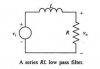
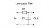
Almost always an RC circuit is used as a low pass filter. Why isn't an LR circuit also used as a low pass filter it, in my option, can effectively work as a low-pass filter because impedance for an inductor is 2*pi*f*L which means high frequency components will get attenuated when passing thru the inductor.
One reason might be that an inductor has relatively high resistance.
The other reason stated by Wikipedia is, "In practice, however, capacitors (and RC circuits) are usually preferred to inductors since they can be more easily manufactured and are generally physically smaller, particularly for higher values of components".
Q2:
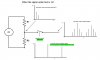
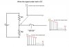
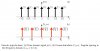
Periodic sampling operation constitutes a periodic impulse train like this. In frequency domain spikes occurs at fs, 2fs, and so on, where fs=1/Ts. The spikes also extend in negative direction - i.e. negative frequencies. Each spike represents a sinusoid having an amplitude 2π/Ts.
Let's first talk about sampling theoretically. Sampling in time domain is multiplication of the impulse train and signal being sampled, and in frequency domain it's convolution of the impulse train spectrum with that of signal being sampled. This text might be useful here - especially the figure at the bottom, Figure 3-5.
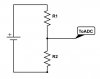
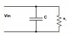
Let's now talk about how sampling is done practically in very simple terms. Suppose that you are sampling the voltage across a resistor. You would use an ADC which connects to the circuit or wire at regular internals, let's talk this interval Ts. Basically ADC connects its internal capacitor for a short time to an external circuit and the capacitor gets charged up. This process of connecting the capacitor to an external circuit for a short time at regular intervals is equivalent to a switching activity where a switch is turned on and off at regular intervals. This regular switching constitutes an impulse train. Do I have it correct?
I'm going to assume that what I said in the paragraph above is correct. We know that an impulse train creates harmonics at regular intervals. Are these harmonics generated in the circuit/wire which is being sampled for voltage at regular intervals? Thank you.
Regards
PG
Q1:
Almost always an RC circuit is used as a low pass filter. Why isn't an LR circuit also used as a low pass filter it, in my option, can effectively work as a low-pass filter because impedance for an inductor is 2*pi*f*L which means high frequency components will get attenuated when passing thru the inductor.
One reason might be that an inductor has relatively high resistance.
The other reason stated by Wikipedia is, "In practice, however, capacitors (and RC circuits) are usually preferred to inductors since they can be more easily manufactured and are generally physically smaller, particularly for higher values of components".
Q2:
Periodic sampling operation constitutes a periodic impulse train like this. In frequency domain spikes occurs at fs, 2fs, and so on, where fs=1/Ts. The spikes also extend in negative direction - i.e. negative frequencies. Each spike represents a sinusoid having an amplitude 2π/Ts.
Let's first talk about sampling theoretically. Sampling in time domain is multiplication of the impulse train and signal being sampled, and in frequency domain it's convolution of the impulse train spectrum with that of signal being sampled. This text might be useful here - especially the figure at the bottom, Figure 3-5.
Let's now talk about how sampling is done practically in very simple terms. Suppose that you are sampling the voltage across a resistor. You would use an ADC which connects to the circuit or wire at regular internals, let's talk this interval Ts. Basically ADC connects its internal capacitor for a short time to an external circuit and the capacitor gets charged up. This process of connecting the capacitor to an external circuit for a short time at regular intervals is equivalent to a switching activity where a switch is turned on and off at regular intervals. This regular switching constitutes an impulse train. Do I have it correct?
I'm going to assume that what I said in the paragraph above is correct. We know that an impulse train creates harmonics at regular intervals. Are these harmonics generated in the circuit/wire which is being sampled for voltage at regular intervals? Thank you.
Regards
PG
Attachments
Last edited: