Continue to Site

Welcome to our site!

Electro Tech is an online community (with over 170,000 members) who enjoy talking about and building electronic circuits, projects and gadgets. To participate you need to register. Registration is free. Click here to register now.

  • Welcome to our site! Electro Tech is an online community (with over 170,000 members) who enjoy talking about and building electronic circuits, projects and gadgets. To participate you need to register. Registration is free. Click here to register now.

Self-shutoff music player with rechargeable batteries for Kids

Status
Not open for further replies.

piwi

New Member
Hi all,

I'm building a kid MP3 player with a few buttons for my 2 years old son.
It's very simple: button pressed-> turn up -> play music -> auto shutoff.

For my first project I selected ready-made boards (with links):
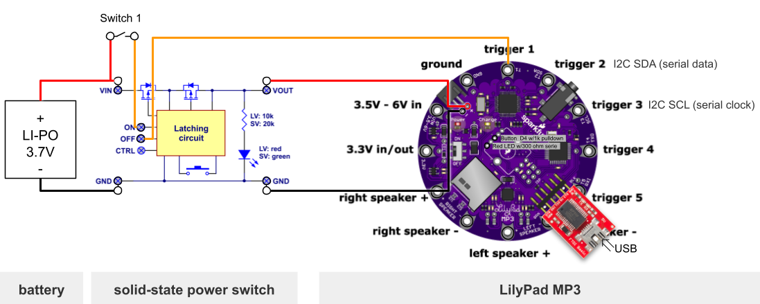
Here is the proposed assembly:
  • place the power switch between the battery and my circuit (red and black wires).
  • connect the "ON" pin of the power switch to the "VIN" pin via a push button so that the system can be turned on by teh user.
  • connect the "OFF" pin of the power switch to the "trigger 1" so that the controller can turn the system off.
pub


When there is just the battery, and not USB cable, this works as expected. The push buttons turns it up, and the `trigger 1` output turns it off.
This gets messy as soon as I plug the USB to the FTDI to recharge the battery.

Here is what I observe when the USB is plugged:
  1. the red led of the solid-state power switch is always on.
  2. state of the latch can be changed from `on` to `off`, and from `off` to `on`. However this is not visible on the led (see #1).
  3. the "charge" led of the LilyPad is always on.
I didn't anticipate that. It raise many questions:
a - How can I validate that the "MCP73831 3.7V Lipo charger" works well through the MOSPHETs?
b - Is it workable or should I consider to replace the "solid-state power circuit" with something else (maybe a relay)?

Tell me what you think.
 
Last edited by a moderator:
Hi all,

I'm building a kid MP3 player with a few buttons for my 2 years old son.
It's very simple: button pressed-> turn up -> play music -> auto shutoff.

For my first project I selected ready-made boards (with links):
Here is the proposed assembly:
  • place the power switch between the battery and my circuit (red and black wires).
  • connect the "ON" pin of the power switch to the "VIN" pin via a push button so that the system can be turned on by teh user.
  • connect the "OFF" pin of the power switch to the "trigger 1" so that the controller can turn the system off.
pub


When there is just the battery, and not USB cable, this works as expected. The push buttons turns it up, and the `trigger 1` output turns it off.
This gets messy as soon as I plug the USB to the FTDI to recharge the battery.

Here is what I observe when the USB is plugged:
  1. the red led of the solid-state power switch is always on.
  2. state of the latch can be changed from `on` to `off`, and from `off` to `on`. However this is not visible on the led (see #1).
  3. the "charge" led of the LilyPad is always on.
I didn't anticipate that. It raise many questions:
a - How can I validate that the "MCP73831 3.7V Lipo charger" works well through the MOSPHETs?
b - Is it workable or should I consider to replace the "solid-state power circuit" with something else (maybe a relay)?

Tell me what you think.

You seem to be trying to fit a mix of things together?, so everything is in the wrong place.

If you want to use the in-built charger and FTDI input, then dump all the latch circuitry.

Can the Lilypad be put into sleep mode?, and be woken by a simple button press? (as PIC's can), in which case that's all you need to do - put it to sleep, and current is low enough not to care about - press the button and it wakes up, does what it needs to, then goes back to sleep.
 
Last edited by a moderator:
Thanks for your answer.

"everything is in the wrong place."
Yep, I agree. The LilyPad MP3 is nice great has restrictions. Now I try to make the best of what I bought.

I played with the sleep modes of the ATmega328P (find code here):
ModeCurrent @3.7V
NORMAL21.5mA
SLEEP_MODE_ADC17mA
SLEEP_MODE_PWR_DOWN17mA
SLEEP_MODE_PWR_SAVE17mA
SLEEP_MODE_STANDBY without BOD17mA

A few observations:
  • The current consumption in sleep mode is much higher than what I expected. I guess this is because of the additional components on the board (charger, amp, codec, SD card & FTDI)
  • All sleep modes are equivalent from the power consumption standpoint.
I investigated a bit further to verify the amp was not ON by default:
Amp stateCurrent @3.7V
AMP OFF21.5mA
AMP ON (without no signal)29mA

Then the AMP was OFF, and can get rid of the power switch otherwise the battery is going to drained in 2 days of sleep mode, which is not acceptable to me.
The original question remains: How can I observer/validate that the "MCP73831 3.7V Lipo charger" works well through the MOSPHETs?

As a workaround to keep my project moving: I came with 3 possible solutions:
  • Replace the li-po battery with regular AA batteries with 4 AA batteries, recharge them with an external charger.
  • Take the LIPO out when it need to be recharged.
  • Bypass the latch circuit with a DPDT switch when charging the battery via the FTDI
 
Well those sleep mode figures are completely useless, it's either not going to sleep at all, or the current is going else where - you need to find where it's going, and why.
 
The Lilypad board has the lithium battery charger circuitry built in to it.

For that to work correctly, it must be directly connected to the battery with no other electronics in line to affect the voltage or current.

You need to either sort out the "sleep" side to get the current down, as Nigel says, or use a mechanical switch or relay to control power so there is no voltage drop or interference with the battery charging system.

eg. You could use something like this:

Feed one coil via a button from the battery positive (with the other end of that coil connected to negative/common) to turn it on and the other coil via a transistor from the output of the board to turn it off, connected as needed.

Add three diodes in series from the USB socket positive to the "on" coil as well, so the battery is automatically switched in for charging when USB power is connected.
 
Well those sleep mode figures are completely useless, it's either not going to sleep at all, or the current is going else where - you need to find where it's going, and why.
I confirm that the processor goes to sleep: it stops executing code. Then I can wake it up and resume execution with a pin interrupt.

Feed one coil via a button from the battery positive (with the other end of that coil connected to negative/common) to turn it on and the other coil via a transistor from the output of the board to turn it off, connected as needed.
Thank you for the reply. I will order a latching relay and give it a try.
Quick questions:
- Can you confirm you suggest using a double- winding latching relay? Because the one you suggested has only one coil.
- Why using 3 diodes in series? Does it provide additional guaranties?
 
Can you confirm you suggest using a double- winding latching relay? Because the one you suggested has only one coil.
Yes, it was supposed to be a double coil type! I'm glad you spotted that,

Try this one: https://uk.farnell.com/panasonic/dsp1-l2-dc3v-f/relay-1no-1nc-250vac-30vdc-5a/dp/2095629

The diodes are to reduce the supply by about 2V so the coil gets around 3V from the 5V USB input.
Each will have a voltage drop somewhere around 0.6 - 0.7V so roughly 1.8 - 2.1V for three in series.
 
Status
Not open for further replies.

Latest threads

Back
Top