Continue to Site

Welcome to our site!

Electro Tech is an online community (with over 170,000 members) who enjoy talking about and building electronic circuits, projects and gadgets. To participate you need to register. Registration is free. Click here to register now.

  • Welcome to our site! Electro Tech is an online community (with over 170,000 members) who enjoy talking about and building electronic circuits, projects and gadgets. To participate you need to register. Registration is free. Click here to register now.

Selecting resistors & capacitors for bandpass filters

Status
Not open for further replies.

Super-Dave

Member
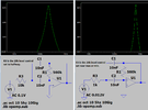
In considering component values for an audio spectrum analyzer bandpass filters (4th order Sallen Key Butterworth) using a TL074 opamps, is there a specific range of values I should adhere to? Is there too high or too low of a value I should stay away from? I don't want weird oscillations, clipping or distortions.

Again, same question regarding the gain. Would it be a mistake to use too low a value (single or double digit ohms) or too high a value (910k-1m) that would overheat, wipe out the op-amp, or result in sub-par performance?

Finally, I know not to use electrolytic caps for bandwidth filtering. I have 2 assortments of poly film caps & ceramic caps. When should I choose one over the other, and why? I have read somewhere that ceramic caps can act as a microphone and introduce unintended input, but when, where, how & why? If I do use them, are there values I should stay away from?

I can't find any info online about this stuff (or I'm asking google the wrong questions). I'm hoping SOMEONE here knows more about this than I do and is willing to share that knowledge.
 
Any opamp has a maximum output current, that it can give, and maintain a full or near-full voltage swing.
That means you cannot use very low resistance (or impedance) loads.

I general, I'd try to aim for a load in the 10K to 100K range, and consider 1K to 1M as limits if at all possible, due to load currents at lower values and leakage-induced errors at very high values,

Capacitor-wise, plastic film is preferred for anything in the signal path; ceramic are fine for supply decoupling.

For your frequency display, using ceramic caps probably would not have any effect, as it's mostly high level and non-audible output - but certainly in low level audio that will ever be listened to, some types can be really nasty!

eg. The cheap NW-700/BM800 and similar fake-condenser microphones that use surface mount multilayer ceramics in the audio circuitry - I consider those an excellent example of abysmal design!
Tap the mic, you can hear the tap/thump through the connected amp; completely disconnect the electret capsule and tap the mic - you still hear the tap/thump, as the multilayer ceramics pick it up almost as well!

It's a combination of simple piezoelectric effect, and "strain gauge" effects when they have a DC bias voltage on them - compression or elongation in line with the capacitor dielectric layers causes a change in thickness, and so capacitance. That modulates the voltage across it in the same way a condenser mic or electret mic does.
 
You do not get a 4th order Butterworth filter if you simply cascade two 2nd order filters.
Go to **broken link removed** for a Butterworth 4th order filter.
 
You do not get a 4th order Butterworth filter if you simply cascade two 2nd order filters.
Go to **broken link removed** for a Butterworth 4th order filter.
Actually, yeah you can.
4-Figure4-1.png

4th order, no inverting, unity gain.

Oh, by the way, your link is broken. But I was able to Google it, it's:
https://sound-au.com/
Maybe it translates differently in Canadian, ey?
 
Your filter has a 2nd order highpass and a 2nd order lowpass. They have gradual 2nd order slopes like I showed.
You probably need 4th-order Butterworth slopes.

Rod Elliot might have the filters on his down-under website with the new name.
 
Found my answers at Elliot Sound's website. Thanks to Audioguru for pointing me in the right direction. I had to dig for it but here it is. I'm cross-posting it here for other 'newbies' such as myself to reference. Good advice & he gives the reasons why.


"Where possible, I suggest that resistors should not be less than 2.2k, nor higher than 100k - 47k is better, but may not be suitable for very low frequencies. Higher values cause greater circuit noise, and if low value resistances are used, the opamps in the circuit will be prematurely overloaded trying to drive the low impedance. All resistors should be 1% metal film for lowest noise and greatest stability. Capacitance should be kept above 1nF if possible, and larger (within reason) is better. Very small capacitors are unduly influenced by stray capacitance of the PCB tracks and even lead lengths, so should be avoided unless there is no choice.

"Capacitors should be polyester or Mylar. Never use ceramic caps except when nothing else is available - if you must use them, use NP0 (C0G) types if possible. Since close tolerance capacitors are hard to get and expensive, it's easier to buy more than you need and match them using a cheap capacitance meter. Absolute accuracy usually isn't needed, but close matching between channels for a stereo system is a requirement for good imaging.

"Unless there is absolutely no choice, avoid bipolar (non-polarised) electrolytic capacitors completely. They are not suitable for precision filters, and may cause audible distortion in some cases. Tantalum caps should be avoided altogether!"
 
Last edited:
The filters on the sound.au website are audio tone controls or speaker crossovers. They have gradual slopes with only 2nd-orders. You need 4th-order Butterworth filters in a bandpass circuit.

Look for a website that has audio bandpass filters made from Sallen-Key 4th-order highpass and lowpass filters.
 
Your filter has a 2nd order highpass and a 2nd order lowpass. They have gradual 2nd order slopes like I showed.
You probably need 4th-order Butterworth slopes.
Correction of the above error:
Each 4th-order bandpass has "2nd-order slopes" (40dB/Dec).
The reason is as follows:
Each bandpass function is the result of the well known lowpass-bandpass transformation.
In this transformation, each lowpass point in the s-domain is transferred into two corresponding bandpass points.
That means: A reference lowpass function of the order "n" corresponds to a bandpass of the order "2n".
Remember: The most simple bandpass (two poles, 2nd order) has a first order slope only (20dB/Dec). Obviously, this reduction in slope results from the zero in the numerator of the transfer function.

Parts values: It is a well established method to consider the opamp during all calculations as ideal. Therefore, the parts values should be in a range where these simplifications will not introduce unacceptable errors.
Hence, all resistors/impedances should be much larger than the opamps output resistance and - at the same time - much smaller than the opamps input resistance.
This restriction leads to the following thumb rule (if possible): Resistor between 1k and 100kohms.
 
Last edited:
A 4th-order Butterworth highpass or lowpass Sallen-Key filter needs 2 opamps, 4 capacitors and 8 or16 resistors.
3rd-order filters might be acceptable and use only 1 opamp, 3 capacitors and 3 or 5 resistors.
 
A 4th-order Butterworth highpass or lowpass Sallen-Key filter needs 2 opamps, 4 capacitors and 8 or16 resistors.
3rd-order filters might be acceptable and use only 1 opamp, 3 capacitors and 3 or 5 resistors.
But I will want a circuit that doesn't oscillate, right? Cause that would be bad, it could stress the op-amp and cause it to fail right? Or does placing a cap downstream of the output cancel that? Because I've notice many of the schematics for spectrum analyzers incorporate them after the bandpass filter. Isn't that why they placed them there, or is there another reason?
 
Case-in-point, the Aaron Cake 3 band analyzer.

I grasp that the diode, cap & resistor following the bandpass filters serve as a peak detector, what purpose does the cap & resistor between the op-amp & peak detector do?
3chspec.gif
 
But I will want a circuit that doesn't oscillate, right? Cause that would be bad, it could stress the op-amp and cause it to fail right?

No, opamps are commonly used as oscillators - but oscillation would be undesirable in a filter :D (or in anything that isn't an oscillator). To quote a VERY old saying about construction methods, amplifiers oscillate, and oscillators don't :D

I grasp that the diode, cap & resistor following the bandpass filters serve as a peak detector, what purpose does the cap & resistor between the op-amp & peak detector do?
The capacitor simply blocks the DC from the output of the opamp, the resistor provide a leakage path to charge the capacitor.

Also you shouldn't confuse yourself with that circuit, as it uses Norton Amplifiers which are somewhat different to all others.
 
But I will want a circuit that doesn't oscillate, right? Cause that would be bad, it could stress the op-amp and cause it to fail right? Or does placing a cap downstream of the output cancel that? Because I've notice many of the schematics for spectrum analyzers incorporate them after the bandpass filter. Isn't that why they placed them there, or is there another reason?
Opamps are frequently made into oscillator circuits and it does not cause failure when the circuit is properly designed.
If an opamp tries to drive a capacitor to ground on its output then it will probably oscillate and might overheat due to the overload from the capacitor. A capacitor is a dead short at a high frequency.

Aaron Cakes circuit has Multiple Feedback Bandpass Filters that have a peak of only a few frequencies which misses many frequencies that you want then has many frequencies at lower levels that you want removed so the bandwidths of the filters are "backwards". The slopes can be very gradual (1st-order).
With a 4th-order Butterworth lowpass and a 4th-order Butterworth highpass in a bandpass then the slopes are steep all the way down to inaudible or invisible but with a fairly flat top with all the frequencies that you want at full power.
 
amplifiers oscillate, and oscillators don't
The way I heard it was: you build an amplifier and it's an oscillator, you build an oscillator and it's an amplifier. ;)
 
Last edited:
Also you shouldn't confuse yourself with that circuit, as it uses Norton Amplifiers which are somewhat different to all others.
I got that, I wasn't going to use the Norton's, but his was the most handy diagram at the time. It's my intention to use TL074's.
Aaron Cakes circuit has Multiple Feedback Bandpass Filters that have a peak of only a few frequencies which misses many frequencies that you want then has many frequencies at lower levels that you want removed so the bandwidths of the filters are "backwards". The slopes can be very gradual (1st-order).
Nor was I intending to employ MFB topology, I'm more inclined to use Sallen Key/Butterworth filters.

Irregardless of the op-amp's or filter type of choice, most all of the diagrams I see online DO use the same series of components following the filters.

Here's another example that's more inline with what I am intending.
AudioSpectrumAnalyzerSchematic.jpg

Again, following the amp we have a series electrolytic cap, grounded resistor, diode, grounded electrolytic cap, and a grounded resistor, all prior to the LED driver. (Yes, it's another MFB, ignore that!) I KNOW the Diode/cap/resistor are the rectifier/peak detector, what I want to know is what the series-cap/resistor between the op-amp & diode is doing? What is their function? Or are they also part of the peak detector? It appears to be a high pass filter, yet it's using an electrolytic cap. I crunch the numbers and it spits out 1.85 Hz? WTF???
 
MFB filters must be fed from a very low impedance like the direct output of an opamp. Yours are fed from a 20k level control that changes the tuned frequency when it is adjusted.
The bandpasses are too narrow anyway to do four frequency bands.

Why do you have a TS921 making a high current ref when the +input currents of the opamps use almost zero current?
The TS921 is not powered anyway.
The opamp +inputs can be fed directly from a resistor voltage divider with a filter capacitor to ground.

I assume that the opamps are powered from +12V and ground, then their outputs are at +6VDC that will mess up the peak detector diodes that need the signal at 0VDC by the DC blocking 2.2uF capacitor and 39k resistor to ground.
Since you use passive diodes instead of active (with an opamp) then the output level from the diode will be nothing when the signal is below about 0.6V so the dynamic range will be very small.

LM3915 and lM3916 VU meter drivers are obsolete and not made anymore. ebay might have fake or defective old ones.

Here is a simulation one of your MFB filters with the level control position changed:
 

Attachments

  • MFB filter.png
    MFB filter.png
    34.9 KB · Views: 252
I KNOW the Diode/cap/resistor are the rectifier/peak detector, what I want to know is what the series-cap/resistor between the op-amp & diode is doing?
If you look at the "VRef" source, it's half the supply voltage.
That is the mid voltage at the output of all the opamps, that any signal is superimposed on.

Without the capacitor, that DC would feed the peak detector rather than the signal.
The resistor keeps the DC level at the peak detector to zero, so only the AC signal is measured.

For full sensitivity, those resistors should ideally all go to a 0.6V reference, like a single diode biased to power with a resistor & a cap across the diode to prevent cross-coupling.
 
First off, this second diagram I posted was yet another bad example I found on the web.
Why do you have a TS921 making a high current ref when the +input currents of the opamps use almost zero current?
The TS921 is not powered anyway.
The opamp +inputs can be fed directly from a resistor voltage divider with a filter capacitor to ground.
I can only assume the original author was using the TS921 to establish a virtual ground for split rail powered opamps. My design will incorporate a dedicated 15+/- DROK microboost power convertor (at 660mv output, it's only capable of driving 3 TL074s, each of which demands 200mv input).
https://www.amazon.com/DROK-Converter-Non-isolated-Regulator-Transformer/dp/B0752TRXDC

Since Audioguru suggests going with an 8th order bandpass filter, I'll need a full quad op-amp for each filter per channel. 5 bands in stereo, I'm looking at 10 opamps, so the 2 I already got from Amazon won't be sufficient to power all ten, I'll need to order another pair.

Then there's the buffer amp, yet another TL074 quad op-amp, each op-amp handling a separate channel: left front, right front to drive the 3 upper bands (treble & 2 mid range), left rear, right rear to drive the 2 lower bands (bass & sub bass). So now I'm up to 11 op amps.

I'm not going to do the virtual ground, nor the LM3915, I'm using transistor driven diode ladder that I built previously (the one with the input bias to restore low sensitivity).

Note to self: sit down and draw out your OWN circuits, quit posting the examples of others. I've written down what I want in stages, nothing complete on a single page.

From what I have gathered from Nigel Goodwin & Rjenkinsgb, the purpose of the series electrolytic cap & resistor it to cancel out any forward DC current, only the bandpass filtered AC sine wave (music), from the LED driver input that may give a false reading on the LEDS. But yet again, the diode FOLLOWING that cap kills off low end sensitivity. So it looks like I am going to have to incorporate a precision rectified peak detector, MORE opamps!

peak detector (1).PNG


Yowza, this thing is going to be huge! The signal is going to have to pass thru 6 opamps before it reaches the lights.
 
I mentioned before that An 8th-order highpass or lowpass Butterworth Sallen-Key filter uses 2 opamps but a 3rd-order one uses only 1 opamp and you should try it.
Replace the transistor with a diode in the peak detector opamp circuit.

Years ago, National Semi made a bandpass filter IC that had everything inside it.
 
Years ago, National Semi made a bandpass filter IC that had everything inside it.
Hmm, I wonder what order that would be, and what topography, Bessel, Butterworth, MFB, or Chebyshev?

Edit: Nevermind, I found it. It was called an MR8, none listed for sale. Looks like it's been out of production for a while and no Chinese clones exist for it. It could be configured into a multitude of configurations (high pass, low pass, bandpass & stop pass) & topologies and even cascades. 4th order, configured as a bandpass it would only have 2nd order slopes.

I want steep 4th order roll-off slopes, a theoretical brick wall from my filters, so it looks like I'm going with a pair of cascaded 2nd order low passes followed by another pair of 2nd order high pass filters. That'll give me a flat wide bandpass with sharp roll-offs & low Q. If I keep them all unity gain, I shouldn't have to worry about phase inversion from the TL074s with a 15v +/- power supply, seeing as the radio driving it all is only 12v limited to 50w peak output. Even with a gain of 2, I doubt the sine wave would swing it out far enough to approach the lower power rail and glitch.
 
Last edited:
Status
Not open for further replies.

Latest threads

New Articles From Microcontroller Tips

Back
Top