Continue to Site

Welcome to our site!

Electro Tech is an online community (with over 170,000 members) who enjoy talking about and building electronic circuits, projects and gadgets. To participate you need to register. Registration is free. Click here to register now.

  • Welcome to our site! Electro Tech is an online community (with over 170,000 members) who enjoy talking about and building electronic circuits, projects and gadgets. To participate you need to register. Registration is free. Click here to register now.

Scr issws

Status
Not open for further replies.

Dr_Doggy

Well-Known Member
thanks to all the help iv had, I have recently completed my "roger the robot" running on my cable box remote,
https://www.electro-tech-online.com/members/dr_doggy-albums-roger-robot.html

and more recently i have added a small prototype coilgun to it, which the robot has full control of (when commanded by the remote). I have also programmed in a lockout code so the charger cannot falsely activate.

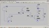
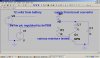
Originally i used the re-load servo to also act as a fire mechanism, but found that inefficient since the discharge blows out and shortens the contacts, so my next plan is/was to use an s4055p SCR instead, however i read that scr directly to the uC is bad idea, and have found that it sometimes works but struggles, so i tried a 9V, which now fires ok, however now i think i have run in to a problem where the scr has fuzed in a closed state.

Im charging 2x 1000uf450v capacitors to about 3-4 hundred volts, and discharging through a very small coil as seen in the photos. My ammo are #6 3/4long machine screws with the heads cut off. and travel about 20-30ft.

but how should i finish this circuit off? am i overloading the SCR's? would 2 work? maybe a larger coil? also how would I wire in a transistor to trigger from the 9v battery(if thats the best way)?

(plan C is to use a camera flash tube, good idea?)
 
Last edited:
i read that scr directly to the uC is bad idea
Agreed. Breakdown of the scr could lead to a fried uC. Better to put a buffer between the two.
i think i have run in to a problem where the scr has fuzed in a closed state.
Are you sure it isn't just that current through the charge-up resistor exceeds the scr holding current, preventing it from turning off? What is the coil resistance and charge-up resistor value?
 
ya, an it has, strange though since the IC controlling it is the 16f6886, however the chip that blew was the 18f controlling it, which is totally isolated except the data wires, i wont waste much time there, but i presume its just cos the 18f is lower voltage

as for the coil it was hard to read, but im guessing about 0.5ohms-2ohms, its hard to tell since i had to subtract from the few ohm resistance from my test leads. however the inductance measures @ 0.05mH. also i wonder if i get a bigger coil, will it pull better (with more turns and less amps?), its already not very powerful,

now i know that gives a starting current of 300/0.5 150-600amps, but i also know thats inital, and that it decays fast, so even though that scr is 40 amp, i know it can take more if its a small enough pulse, but thats all i know and dont know how to get a "burst current rating"

also im sure that it is not a holding current stopping it since even after the scr has been disconnected and reconnected it does not unlatch, i even tried disconnecting it from caps and putting a -9v on the gate.

originally i thought of a scr as a high power transistor, but since using it and hearing that little click inside of it, i now think of it as more of a relay, weather this is right or not.

oh, an im not too sure, but i dont think im using or understand "charge resistor", i am using 16F with transistor to drive a boost converter, @ 12v1.5amps here is the thread:
www.electro-tech-online.com/threads/first-boost-converter.131512/

and this is the closest schematic i can find for my converter:
https://electronicdesign.com/site-f...ign.com/content/content/61670/61670-fig-3.jpg
, either way, the charger pumps the volts to the HV caps, isolated by diode so no back fire, and the HV caps are connected direct to the coil rite now
 
im sure that it is not a holding current stopping it since even after the scr has been disconnected and reconnected it does not unlatch
So the scr is dead.
originally i thought of a scr as a high power transistor, but since using it and hearing that little click inside of it, i now think of it as more of a relay, weather this is right or not.
If the origin of the sound was indeed inside the scr then that was the scr dying :(
 
it always clicked when latching and unlatching when it was working, but now its not and stuck closed,

so they are dead,

but that is why im here, to preserve the life of my last one!
 
it always clicked when latching and unlatching
Probably internal breakdown. If the coil resistance is > 0.5Ω then discharging 2000uF from 300V should be well within the rating of your s4055p (according to its Littelfuse datasheet) and the noise spells trouble. Did you get the scr from a reliable source?
 
well that is good that i got that spec right anyway, btw maybe you can show me how you came to that conclusion, i know that 300/.5=600amps, but how would i calc that time thing, or maybe there is a spec on the datasheet that i missed for a burst current?

i got the part from digikey, and it did work a few times...
for now though lets ignore the clicking, it may be a error on my part, how should i proceed with the hookup? can i do this with a simple pnp transistor and resistor? btw my supply is 12v, trigger switch is 5v from pic and for all intensive purposes pls consider me a newb at this(scr's) so if there is anything special i should know pls mention.
 
maybe there is a spec on the datasheet that i missed for a burst current?
IIRC it was Fig 10 that showed data for capacitor discharge.
how should i proceed with the hookup? can i do this with a simple pnp transistor and resistor?
It would help if you post a schematic of your present set-up.
 
You cannot fire an SCR directly from a CPU pin reliably. You are effectively switching on a transistor junction so like a transistor you will need some form of current limit on the output of the firing port in the form of a resistor or opto isolator. The SCR will likely clamp the output of the CPU to 0.7V which isn't recommended.
 
i will spare the other details but
Q1 = SCR
L1 = COIL
C1 = 450V CAPS
R1 = VARIOUS RESISTORS TESTED

basically iv been approaching this as an "Educational Experience" meaning i have been using random base resistors have been connecting them to random sources , ie 5v,11v or a 9v test battery connected with common ground,
at first i did not use any gate resistor, which probably led to the failure of first scr
 

Attachments

  • coilgun.jpg
    coilgun.jpg
    98.3 KB · Views: 163
If you don't have a simulation model for an scr you can download one from the LTspice User Group at Yahoo. Choosing resistors at random may be educational, but you will likely fry a lot of scrs in the process :). Better to check the scr's datasheet to determine the gate sensitivity and calculate the required resistor value accordingly.
 
looking closer i cant believe this, but point blank it says surge current up to 650v, also that the gate current is 40 ma, so that means i should use 12v/0.04 = 300 ohms for R1?.

also i have put in a 2n4403 pnp, and im not sure but i think the datasheet says a gain of 100? so that means 40ma/100 = 0.4ma for the pnp gate, so a resistor of 5/0.4ma = 12kohms between the pic and pnp gate?
pls double check, i am just guessing at this and not so good with pnp yet

mind you i dont know how to use spice yet, and just using for simple diagrams, here is the update:
 

Attachments

  • coilgun.jpg
    coilgun.jpg
    73.6 KB · Views: 184
The pnp is wrongly configured. Perhaps easier to use an npn? It would be safer for the PIC, however, if you used an optoisolator to trigger the scr, as WTP Pepper suggested. Even if you do manage to trigger it, how are you going to turn it off? Unless you have some turn-off arrangement the current from your boost converter will continue to flow through the scr and prevent the cap from charging.
 
it would be easier to use npn, i will get a optoisolator if required but would rather use a transistor since i have lots of those, i m not sure how to arrange the npn properly either, i have tried but i have that feeling im doing it wrong


is there perhaps a wiring diagram i can go by?


(my problem with the transistor is that when i wire npn, i usually put the transistor at the ground side and the resistor on the collector, which is opposite to this example:
**broken link removed**
what happens though when i use the given example? does that change what i need to feed in at the gate at all?)
would my previous diagram work if i simply changed the pnp to npn?
 
ALSO i have another question, a little off topic, i am looking at this circuit:
**broken link removed**

would it actually work?? i see how the SCR fires , but how does it shut off, will just a lack of current do it? or does the neon light drain the gate, are there components i could use instead of the neon?


really i want to do this:
https://www.youtube.com/watch?v=4l1PfmTheFM
maybe you could understand what this guys saying and point me to a schematic?
EDIT: i think i found it, a "self resonating circuit"

btw, im interested more in how it works than what it does, or doesnt do...
 
Last edited:
Hello,

You can try using the NPN as a current amplifier with a current liming resistor for the SCR gate.

However, there may be another problem that is more significant than overcurrent for the pic pin. When the SCR turns on it connects a coil to a capacitor charged to a high voltage. There is also a little resistance in there due to the coil resistance and the capacitor ESR. Now if that resistance is high enough naturally, the RLC circuit formed there may be overdamped, in which case you are good to go. But if it happens to be underdamped (very very possible), then you could see oscillation that results in voltages much higher than the rating of the SCR. If we look at it another way we see a boost converter output at the SCR anode, which means high voltage there which could be higher than the SCR can take. Even voltages slightly higher than the SCR rating should be avoided as they damage the die. So what you need to do is test it at a lower voltage, like 100 volts or even lower like 20 volts. If you see overshoot at the 'collector' of your schematic, then you can extrapolate that value to the true intended operating voltage and see if it works out ok for the SCR. You may need a higher voltage SCR or introduce a little more resistance in the circuit. Usually we want to avoid extra resistance in these kinds of circuits like the plague, but if the SCR blows out every time then it's beat anyway. So you'd have to test this by looking at it with a scope and LOWER cap voltage like 20v, 50v, then 100v, etc. Most of the time we'll see a linear relationship between voltage and overshoot, so testing at 20v should be close to what happens with 200v except of course proportionally higher.
 
i think im ok with dampening, i put my scope on both the scr anode as well as the supply rail for the capacitor, and did not detect any spikes or ringing, just a straight discharge.

while testing the scr, triggering the gate with a 9v battery i can confirm the clicking when it fires under normal operation, i actually tested it up at 80 volts and using the battery direct to the gate, i tried with 156 ohm resistor but only got partial fires, but i believe that to be due to a dead 9v , the scr again seems to fire properly, and is unlatching after discharge then returns to 12v ( which is flow through from when the converter driver is off but converter powered )

i will try again with the npn later.
 
Hello,


Ok then it sounds good. Just have to watch out how many times you try to discharge in a given period. Also make sure you have a gate resistor to ground.
 
The circuit in post#15 won't work.
Here's one possibility. Note R3, which limits the cap charge current so that the scr can turn off once the cap has discharged. The downside is that charging takes ~ 30sec.
SCR_trigger.gif
 
thnxx, schematic helps a lot, and i see my errors, but i wonder why do we put in R4? should i consider it as a pull down resistor, and does it change value at gate?


......BBL ordering optical isolator.....
 
Status
Not open for further replies.

Latest threads

New Articles From Microcontroller Tips

Back
Top