Continue to Site

Welcome to our site!

Electro Tech is an online community (with over 170,000 members) who enjoy talking about and building electronic circuits, projects and gadgets. To participate you need to register. Registration is free. Click here to register now.

  • Welcome to our site! Electro Tech is an online community (with over 170,000 members) who enjoy talking about and building electronic circuits, projects and gadgets. To participate you need to register. Registration is free. Click here to register now.

How to fire the SCR's

Status
Not open for further replies.

avz

Member
Hi, I'm looking for a way to fire the scr's so that it will be able to control the welding current. I know that it's possible to buy a cheap inverter welder, but it interests my more for learning to make this work. I do apologize for the poor quality of the circuit attached. as you can tell, it was drew by hand. the diodes D1 and D2 and the SCR's are rated 200A each and I'll appreciate you suggestion for a circuit (simple as possible) that will turn them on and off and enable them to control the welding current.
 

Attachments

  • IMG_20220226_0001.pdf
    99.5 KB · Views: 234
Continuous on or off is simply a matter of gate current on or off (relative to the cathode).

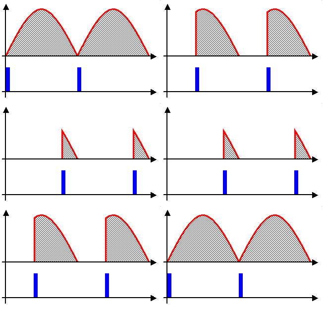
To give continuous control, you must trigger the thyristor with a gate current pulse at the correct time in every AC half cycle; the later in the half cycle, the shorter the time before it turns off (at the AC zero crossing), the earlier in the half cycle, the longer the time - so more power to the load.

That's how simple "light dimmers" work, but from a manual control.

For a regulated current, you need a rather more sophisticated control system with enable, current setpoint and current feedback to continuously vary the phase timing to suit the demand.
 
This partly repeats what rjenkinsgb said. I had drafted this earlier and forgot to hit "post".

It's not simple.

You need a circuit that can measure the current, and then use that to decide when to fire the SCRs. You need some sort of zero-crossing detector, which will tell you when the voltage has got to zero, to give a starting point for the time to turn on the SCRs.

The data sheet for the SCRs should tell you how much current they need to trigger.

A separate power supply for the control circuit will be needed.

With currents of the order of hundreds of Amps, if something goes wrong, it will go very wrong very quickly.

I would suggest starting with a small transformer, that will cost nearly nothing, and will stand being shorted for at least 10 seconds. Once you have a control system working for a load of a few hundred mA, then you could look at the full-power transformer.

Even with a known control system, I would put resistors in series to limit the damage if you control system fails.
 
You will need to introduce a suitable resistor between the Gate and Cathode of the SCR's to avoid random triggering due to Transients or Leakage.
 
Status
Not open for further replies.

Latest threads

Back
Top