referring to a previous thread with several schematic diagrams, I wanted to build an rpm switch that activates a device when a certain engine rpm is reached and is above that threshold, and deactivates when engine rpm drops below the same threshold.
from this thread: https://www.electro-tech-online.com/threads/motorcycle-rpm-switch.18122/
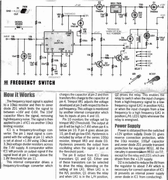
I think this circuit is what i need. I also need some help regarding the VR settings. I want a circuit to close a switch (Relay 1 NO terminals) when the input detects a preset RPM.
Am I correct that if i select LK1 to L/H position, the relay will be energized if pin8 of IC1 is high? How will i adjust VR1 and VR2 so the relay will be energized if input at pin1 is above 10Khz?
from this thread: https://www.electro-tech-online.com/threads/motorcycle-rpm-switch.18122/
I think this circuit is what i need. I also need some help regarding the VR settings. I want a circuit to close a switch (Relay 1 NO terminals) when the input detects a preset RPM.
Am I correct that if i select LK1 to L/H position, the relay will be energized if pin8 of IC1 is high? How will i adjust VR1 and VR2 so the relay will be energized if input at pin1 is above 10Khz?
