Continue to Site

Welcome to our site!

Electro Tech is an online community (with over 170,000 members) who enjoy talking about and building electronic circuits, projects and gadgets. To participate you need to register. Registration is free. Click here to register now.

  • Welcome to our site! Electro Tech is an online community (with over 170,000 members) who enjoy talking about and building electronic circuits, projects and gadgets. To participate you need to register. Registration is free. Click here to register now.

Motorcycle RPM switch

Status
Not open for further replies.

mattpatt

New Member
Hi, I'm new here, and also new to all things electronic.

I want to build an rpm activated switch for my motorcycle and I've looked through the various threads here, but I'm still a little lost.

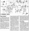
I bought a frequency activated switch that uses an LM2917N IC and it works like a dream, but when I look at the "speed switch" schematic on the data sheet it makes the switch I bought look like overkill!

Basically what I'll be looking for is to be able to switch an LED on at let's say 10,000rpm (166.66Hz), but I'd like it adjustable so that I can pick the point that it's activated to an accuracy of approx. 100rpm (1.66Hz).

I suspect that to achieve this accuracy will mean that the range of operation is limited. If this is the case, how can I then adjust the range of operation?

Any help that you can offer will be much appreciated.
 
Welcome aboard "mattpatt"

Can you show us the schematic you have ?
 
I'll have to scan the schematic of the kit that I bought and send that to you.

The "rpm switch" that I was hoping to build would come from the schematic on the LM2917 National data sheet for the speed switch that has been discussed on this forum in other threads.
 
If you are referring to the speed switches shown in the LM2917 datasheets it seems unlikely that you'll get the accuracy or resolution you need. Do you really need that kind of accuracy? The circuits depend on values of R and C for the timing. You could construct the circuit so that with the aid of some calibration equipment you could adjust it to within 100 rpm but the calibration won't last long. Temperature changes, among other things, will cause the circuit to drift out of calibration.

It would seem that you could get the accuracy/resolution you need digitally. You'd need to measure the rpm then compare that value to your target point- when equal to or in excess of you'd like the light. "Equal to" would be unreliable as you might only be at that limit for a moment.

My guess is that someone has already done that with a PIC or some other programmable device. The question is whether or not they've documented it and are willing to share the project.
 
The accuracy of 100rpm that I desire is pretty important to me. The shift light idea is only the start of what I would like to use this circuit for as I see potential for a host of other components that could be triggered by this.

Just out of interest, what sort of accuracy could I expect using the speed switch on the data sheet?
 
If you use metal-film resistors, a cermet trimmer resistor, metalized plastic film capacitors and a voltage regulator IC replacing the zener diode then a repeatable accuracy of about 0.5% is quite possible.

Check to see if the charge time of the capacitors exceeds the accelleration of your bike. You don't want the circuit to give a delayed output.
 
Sorry, still haven't got around to scanning the various schematics for this project, but I'll try and get it done today. This nasty work thing keeps taking up all my time!

I build up a circuit last night using the 'speed switch' schematic and I think I got it somewhere near, but had no luck in lighting my LED.

I'm using a 14 pin 2907 ic, not the 8 pin as shown in the data sheet. maybe I hooked something up wrong along the way. It didn't cook the ic though as I then fitted the same ic into the commercial frequency switch I have and it worked fine. maybe I should just stop messing around and blatently copy the one I have that works. The thing is that I want to make it smaller and if I can do this with a minimum of components then I'll be happy.

Maybe someone has an idea of a circuit that will get me pointed in the right direction, ie. a circuit that will make my LED turn on at say 10,000rpm (166.66Hz), with adjustability of 1,000rpm either way.
 
The 8-pins device works with "variable-reluctance" sensors that have a voltage that swings positive and negative.
The 14-pins device works with breaker points whose signal never goes negative.
 

Attachments

  • lm2907-2917_183.gif
    lm2907-2917_183.gif
    30.1 KB · Views: 1,947
Does that mean I can't use my 14 pin 2907N ic?

The frequency switch I purchased uses a 14 pin 2917N ic and this seems to work with my variable reluctance set up.

maybe I'd better get the schematic over to you toute suite for your perusal.
 
If your variable reluctance setup has its common wire grounded then you can't use the 14 pin IC.
 
A Possible Solution (LONG)

Hi Mattpatt,

Just seen your post - love the concept!!!

Have been giving your 'problem' a bit of thought please find enclosed a possible solution - no specifics or schematics just a purely brainstorming exercise - see what you think.

I do think a Microcontroller would be the easiest answer - only assuming you have all the kit necessary and the programming experience. How about a LOGIC solution. (albeit with s**t loads of comparators!!!

I think you have a couple of problems to sort out.

The main one being the resolution and conversion values for the circuit i.e. Pulses to RPM values - Ill leave you to sweat over that one.
Secondly, The actual value of RPM switching i.e. LED light to at 9074 RPM again this is related to the above resolution problem.

Reference my enclosed PDF

Please verify my values!!

Taking your points/pickup pulses via the Opto Isolator (signal/level conditioning not withstanding) feed this a frequency multiplier to increase the resolution of circuit. (16 bit counter = 65536 pulses assuming 12000 RPM multiplication factor of 5) therfore 1 RPM = 5 pulses

"Lost Spark Ignition" system needs to be considered in the above multiplication factor.

These pulses feed the 16 bit counter which is reset when the ignition is turned on - count = zero. Engine is started and the counter starts to count

These pulses are fed two two 8 or 16 bit word length Tri-state buffers. The actual length and connection being SOT determined for best response (ideally 16bit). Two buffers are required to determine which 'way' the revs are heading so as not to have a counter that actual counts the ignition pulses but arbitarily mirrors them to give a generic binary number which is to be compared.
One of these buffers has a small delay (Again Select On Test) possibly achieved by using 3/4 inverters (propergation delay) to allow different counts to be compared. In practice a small bistable might be needed or alternatively the Output Enable fed from D1 (again SOT)

The resulting value from the comparison A<B, A=B, A>B is fed back to the counter to either allow the count to continue upwards (increasing revs) to count downwards (decreasing revs) toggling the CE (Chip Enable) line to stop count (possibly via logic gates onto the clock pin depending on counter model)

Meanwhile the values produced by the 16 bit counter are fed to another comparator, this compares the 16bit binary word to a predefined value via BCD switches (or similar). If the switch value is higher than the count value a green LED would be on (can be omitted) if count is equal to or greater than switch value then the red LEd (or buzzer) would light.

Using this system and including an additional comparator a range of LED's could be illuminated at different RPM's (akin to F1 steering wheel!!!!!!!)

A Microcontroller would be considerably less work not to mention soldering!!!

Hope this helps
Dotnet
 

Attachments

  • rpm_block_diagram.pdf
    54.3 KB · Views: 704
Here's what I have. This is the schematic for the frequency switch.
 

Attachments

  • image-06_schematicb.jpg
    image-06_schematicb.jpg
    154.9 KB · Views: 2,183
I couldn't find Silicon Chip magazine's entire article in Google, but it looks like it is designed for breaker points, not a variable reluctance pickup since its zener diode shorts the negative swing to ground. It might work OK with a variable reluctance pickup though.
 
Why Bother !!!!!!!!!!!

To mattpatt,

I notice you have 2 posts after my submission -

It would have been nice (if not down right polite) to have acknowleged my reply even if it was 'thanks but no thanks' or 'it's not what I'm looking for' but something


Don't come here ask for people advice then ignore them, especially when they they give up their time (7Hrs) to try and help.

Some people !!!
 
Hi grumpy DotNet,
You didn't post a pic of your circuit and it sounded kinda complicated, so I didn't look at it until now.
It is way too complicated for a simple shift-light tachometer circuit. I shrunk the size of your circuit and here it is:
 

Attachments

  • dotnet_s_circuit.png
    dotnet_s_circuit.png
    49.7 KB · Views: 1,297
Hi audioguru,

1.) Not grumpy at all
2) The comment was not directed at you!

Forums are by and large a community of goodwil! Pllease and thank-you are things called MANNERS and are appreciated by people who give up there time.

With reference my design - complicated - I couldn't agree more (it wasn't intending to be when I started thinking about it!!! :oops:

But it might give the original poster an idea on how to produce his (or her) own work to solve a problem instead of abitarily reproducing someone elses.

But the circuit would solve a number of 'issues' (if it worked :) ) frequency drift, component values, interfacing with ignition etc it would also allow for complete 'tweaking' of 'red line' values not to mention the possibility pending red line approaching and offer machine and cylinder number independancy (sorry for bad english).

It would also allow for an easy project to work on and fault find espeacially if your new to electronics. But as a stevez said this would be ideal for a MCU based project.

Being a biker myself I can think of three reasons why mattpatt was after an RPM switch - Racing, Tweaked engine ( :wink: ) or an interesting project. If it is the one of the first two he (she) needs reproducable accuracy.

With refernce to the diagram I'm not completly sure how to show the diagram properly, and as I have noway of deleting the post after I sent it I erred on the side of caution.

A non grumpy Dotnet Signing off
 
Hi again non-grumpy DotNet,
Yeah, an MCU based system could anticipate a shift point and could even allow you to record RPM and accelleration during a race. Maybe you could send it back to the pits as telemetry.

My new car has electric power steering so I think its ECU records my steering as well as speed and braking just prior to a crash. Then the cops and the other guy's lawyer will see how many 360's I did to try to avoid the other guy's stupid mistake. :lol:

I saw a guy drive his car through a red light into the rear side of a propane-powered taxi. He didn't slow-down nor swerve. He was lucky to wake-up without injury nor a spectacular explosion!
 
Dotnet, I don't fully understand your block diagram, but I got stuck on the frequency multiplier. Do you have a method for doing this? I believe that the wide range of RPMs, considering that the frequencies involved are low, means that a PLL, even if you could make one work over the range, would have significant delay in tracking the input frequency.
 
And instead of frequency multiplication and PLL stuff, can one use the rising edge of the speed signal to gate a fast running clock into the 16-bit counter(actually this is a form of frequency multiplication)?

In this arrangement, the period of the input frequency is being measured so one should arrange the magitude comparator to compare for the recipical instead.
 
Status
Not open for further replies.

Latest threads

New Articles From Microcontroller Tips

Back
Top