grrr_arrghh
New Member
Hi
I have been considering building a continuity tester for Cat5 network cables (which have 8 individual wires) for a while, but can't come up with a suitable solution.
Most of the designs I have seen rely on two of the individual wires to be intact, in order to complete the circuit, and light the LED, telling you that pair is ok. Obviously, you don't know which of the two wires (or possibly both) is not connected.
The other way I have seen it done is to have a common ground, or common anode, and have 7 LEDs connected to the other wires. However, this won't show up a problem if the common connection is the one that is out. I suppose I could feed the outputs into logic, then if none of the other wires returned an output, the logic could give an output showing that it was the common that was out. But what if it wasn't - what if it was the other seven that were out? It seems like a bit of a bodged way to do it.
In both methods, there is something that is plugged into the other end of the cable - either simply wires connected together, or sometimes transistors and the like - I am not bothered about which, however I would rather that it drew power from the main tester unit, instead of having its own power supply.
Only other requirements are that the output display should be on the main tester unit. Power should be 9v or less (need to use batteries), adn as such I would prefer to use only CMOS type ICs.
Anyone any better ideas?
I would prefer to avoid PICs, because I don't really know alot about them, and I don't have the cash to start learning!!
Thanks
Tim
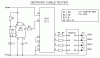
P.S. Below is an example of the sort of circuit described in paragraph 2.
I have been considering building a continuity tester for Cat5 network cables (which have 8 individual wires) for a while, but can't come up with a suitable solution.
Most of the designs I have seen rely on two of the individual wires to be intact, in order to complete the circuit, and light the LED, telling you that pair is ok. Obviously, you don't know which of the two wires (or possibly both) is not connected.
The other way I have seen it done is to have a common ground, or common anode, and have 7 LEDs connected to the other wires. However, this won't show up a problem if the common connection is the one that is out. I suppose I could feed the outputs into logic, then if none of the other wires returned an output, the logic could give an output showing that it was the common that was out. But what if it wasn't - what if it was the other seven that were out? It seems like a bit of a bodged way to do it.
In both methods, there is something that is plugged into the other end of the cable - either simply wires connected together, or sometimes transistors and the like - I am not bothered about which, however I would rather that it drew power from the main tester unit, instead of having its own power supply.
Only other requirements are that the output display should be on the main tester unit. Power should be 9v or less (need to use batteries), adn as such I would prefer to use only CMOS type ICs.
Anyone any better ideas?
I would prefer to avoid PICs, because I don't really know alot about them, and I don't have the cash to start learning!!
Thanks
Tim
P.S. Below is an example of the sort of circuit described in paragraph 2.
")
