Continue to Site

Welcome to our site!

Electro Tech is an online community (with over 170,000 members) who enjoy talking about and building electronic circuits, projects and gadgets. To participate you need to register. Registration is free. Click here to register now.

  • Welcome to our site! Electro Tech is an online community (with over 170,000 members) who enjoy talking about and building electronic circuits, projects and gadgets. To participate you need to register. Registration is free. Click here to register now.

Old continuity tester

throbscottle

Well-Known Member
Has anyone come across, or maybe actually owns, a Vitrex continuity tester of (guessing) 70's or 80's vintage? I ask because I inherited one as part of a kit that was my father in law's, and the wire-end battery contact is completely corroded away. So I'd like to find out what kind of shape it was. Because I like making old stuff work again, obviously.

I know I could just cut out a piece of metal and call it a fix, but the 2 pieces of plastic it was attached to are relatively complicated, so I'd like to re-create it something like the original and attach the wire in the intended fashion if I can.
 
Would be good to see some images for the members to suggest modern available in-the-market battery holders that could be used in replacement to yield a better-than-factory restoration.

Perhaps the corroded contact alone is canibalizable from something else.
 
Keystone Electronics has a large variety of pcb-mounted contacts. Looking at the pictures may help you figure out what was there
 
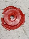
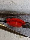
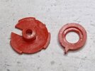
Ahh. I didn't give enough information. This is a very simple (but nicely made) battery and bulb in a tube with a point on one end and a wire with clip on the other. I'm hoping someone has encountered the same make and model so they might know what the contact actually looks like. You can see from the photos it was attached to 2 fairly complicated (for what it is) bits of plastic. The contact assembly is held against the battery by a spring.

My best guess so far is that the wire goes through the slot in the big disk, wraps around the middle and would have been soldered to a circular contact riveted in the middle. But, what's the little peg on side of the small piece for, and why are there 3 notches in the big piece, and why has it got ever such a slightly raised edge? These are the questions that keep me up at night...

IMG_20230428_221048.jpgIMG_20230428_221147.jpgIMG_20230428_221309.jpg
 
I'd guess the smaller part had just an eyelet rivet, stud contact or similar in it, soldered on the end of a wire? eg. Similar to in an inline fuseholder?


What's on the other side of the large piece? I don't see a reason for the tube part, unless that is supposed to locate in the spring you mention?

Without seeing how those possibly fit & locate in the device body, it's still guesswork.

0039521_inline-glass-fuse-holder-with-terminals.jpeg
 

Latest threads

New Articles From Microcontroller Tips

Back
Top