Continue to Site

Welcome to our site!

Electro Tech is an online community (with over 170,000 members) who enjoy talking about and building electronic circuits, projects and gadgets. To participate you need to register. Registration is free. Click here to register now.

  • Welcome to our site! Electro Tech is an online community (with over 170,000 members) who enjoy talking about and building electronic circuits, projects and gadgets. To participate you need to register. Registration is free. Click here to register now.

RF Power Amp (Share)

Status
Not open for further replies.

Space Varmint

New Member
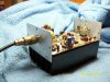
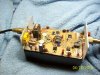
Thought you guys might to look at this new power amp I just finished up. It's a 200 watter for the HF bands. The finals are 2SC2879's. They are an up grade from some Motorola transistor that is 100 watts. I have heard stories that you can get 150 watts from each. The drivers are MRF475's and the other TO220 packages in the center of the board are LM317's for the bias to the class A linear finals. Anyway I wanted to share this because of course I'm always gonna look for sample designs and could not find anything that looked like a real push-pull at these frequencies and or power levels. I found one or two designs that used an LR network to shift the phase but this would be a poor broadband amplifier because the inductance would change with frequency so I drafted this up off the cuff and had to do very little to change it once put together. All cores are Amidon number 43 mix. The signal paths use balun cores and the toroid cores are just chokes used to clean up the power bus along with various size filter caps. I put .01uf caps all around the board from power to ground.

edit*

I thought I should mention the symbols for the final power transistors. They are custom and I had to do them with two emitters in Eagle or it would not pick them both up in the board Gerber file. The finals are SOE (Silicon Opposed Emitter) which are the big round pill looking transistors with gold plated fins and it has 4 of these flat fins because two of them are emitters which are usually grounded and so they make a nice ground plane when soldered to the PC board ground plane. You always know the pin configuration because the collector is cut at a slant and the opposing emitter means they are straight across from each other so that leaves the base across from the collector.
 

Attachments

  • Push-Pull.gif
    Push-Pull.gif
    20.1 KB · Views: 474
  • 100_1543.JPG
    100_1543.JPG
    342.8 KB · Views: 438
  • 100_1540.JPG
    100_1540.JPG
    379.5 KB · Views: 602
Last edited:
this circuit use the push-pull for RF... can u please post about principles of "cutting angle" compose of A,AB,B, C,D,E. then to compare.
 
this circuit use the push-pull for RF... can u please post about principles of "cutting angle" compose of A,AB,B, C,D,E. then to compare.

Well, I have it set up class A. Actually you establish it by the Idc of the transistors. That is the standing base current. But I can actually use the voltage and set to where it just turns on, on both. You can also put a scope on it. If I turn both off then turn one on I can actually see pulsating DC at the output. If I turn it higher than one side will amplify the whole signal but you will have less voltage than running both. So if you use the scope you can adjust to where you see pulsating DC from one then lowly turn on the other and you will have a large voltage amplitude at the output. Then just peak them both. If you have one set up to amplify more than half the signal you will get a lower output.
 
Is there a typo on your schematic? C5 looks like a virtual RF short (.1uf) to ground. at the HF band. R4 seems like a real low impedance (5 ohm).
 
Is there a typo on your schematic? C5 looks like a virtual RF short (.1uf) to ground. at the HF band. R4 seems like a real low impedance (5 ohm).

let me look. Be right back. How you doing Mike? :) By God you right Mike. C5 is not even in the circuit. I think I meant it to be 100pf but I already have one. The 5 ohm is actually a 10 ohm on final design. Used to lower the input impedance. I sketched up the schematic first and guess I didn't get all my corrections in which were very few anyway but that's a biggy the .1uf on the base. Should have caught that. Thanks Mike.
 
Last edited:
In fact the pictures are the final design. So there are no caps on the base and 10 ohms from base to ground. I also changed it to 33 ohms in series to the bases of both for soother adjustment.
 
You might also consider adding a RF choke on the anode of D2 and D3.
 
Last edited:
You might also consider adding a RF choke on the anode of D2 and D3.

That sounds like a good idea but I've never seen that technique used. I see your point though, to offer more impedance to ground and at that power level it might add a couple of watts. I'll bare that in might but as you can see I also removed the diodes. Normally the diodes that would have been in it are for maintaining a steady bias. They are used for temperature compensation and should be mounted securely to the heat sink. I just took them out. I'll put some lock tight on the pots and cross my fingers...lol. Anyway I went ahead and updated the schematic.
 

Attachments

  • Push-Pull.gif
    Push-Pull.gif
    19.7 KB · Views: 582
Last edited:
Got one issue. Mike or anyone with experience, what I got is a bad heat issue. In fact I forgot one part in my update. R16. The problem is the DC current causes the connection to get too hot and unfortunately I did not put a bolt in the mechanical design. Does anyone have a suggestion? Something I can do after the fact to secure the connection. Will increasing the gauge help? I don't want to lower the power but might have to. I hopped up the drive and the amp followed suit no problem but it's getting too hot for that collector connection.
 

Attachments

  • Push-Pull.gif
    Push-Pull.gif
    19.9 KB · Views: 218
I should think R16 is not needed.
 
I should think R16 is not needed.

I'm finding out that some of it is actually reflected energy to my surprise. Still got a couple of things to work out. Not getting full power and it quit excepting power from the transmitter. Looking at driver transformers.
 
Something wrong about R16. If it really is 10 ohms how are you getting 100 to 200 Watts out? How are you getting more than 1.3A of collector current with 10 ohms on 13.8V?
 
Out of curiosity, just what current draw are you seeing from your DC supply? How is your test setup configured? At the very least, you should have a in-line watt meter followed by a good 50 ohm dummy load. I would recommend the Bird 43 watt meter if you can find a good deal on one.

**broken link removed**
 
Alright! Is that your Bird watt meter? Wish I had one. I got a Diamond. They're pretty good. Anyway I was just concerned with the heat problem so I might take it out when my output network is done. Here's where I made a big Boo-boo which I will update the schematic when done. I totally forgot. I need much more current on the base of the drivers. I have a single ended like 60 watt amp I built and used for a while using the same driver and I checked the bias and this is way off!! Other than that the schematic is straight. Just the values are screwed but I'm gonna try something different on that base bias. I matched up some diodes and I'm gonna use your technique Mike with the chokes.
 
Last edited:
Yes, Mike. If there's 10 ohms in series with the collector supply, I would expect no more than 8 watts of RF from 13.8V.
 
It may be important to point out to other readers that these numbers represent a DC point of view, and that AC impedance has a different role in calculations. Did I say that right? :)
 
That's good work guys! That chart looks a little funky to me but 8 watts sounds about right. I think it's time to pull that 10 ohm. I got something else going on too. That transformer is getting too hot. Normally I stack 1/2 inch diameter toroids into two columns but Amidon recommended this square thing.
 
Status
Not open for further replies.

New Articles From Microcontroller Tips

Back
Top