Continue to Site

Welcome to our site!

Electro Tech is an online community (with over 170,000 members) who enjoy talking about and building electronic circuits, projects and gadgets. To participate you need to register. Registration is free. Click here to register now.

  • Welcome to our site! Electro Tech is an online community (with over 170,000 members) who enjoy talking about and building electronic circuits, projects and gadgets. To participate you need to register. Registration is free. Click here to register now.

revised control board

Status
Not open for further replies.

charlie_r

Member
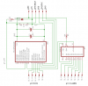
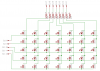
As was suggested by blueroomelectronics, I have revised the control board for my LED light system, to avoid a possible dim light output problem.

If I could get a review by several of you more experienced electronics gurus....

Couple of Questions:

1. Do I need to put pull-ups on my switch inputs [RA5, RB5, RB6]?

2. Are the 47KΩ resistors between the outputs and the ULN2803s too high resistance or will they be OK?
 

Attachments

  • ctrlbdr1.png
    ctrlbdr1.png
    27.6 KB · Views: 290
Not sure you need the 47K resistors. You should be able to drive the 2803 darlington arrays directly.
BUT they are all cathode drivers, you need PNP transistor to drive the anodes.
 
I wish you continued the same thread as before because here you start half-way through and we don't know what your circuit is supposed to do.

Do you have an array of LEDs in rows and columns?
Are the LEDs burned out by the ULN2003 ICs? There are no current-limiting resistors.

The ULN2003s cannot drive the LEDs anyway because their output only goes low. You need the rows to go high since the columns go low.

The input switches are not shown (do they go to ground?) then they probably need a pullup resistor.

The 47k resistors cause trouble and are not needed. The ULN2803 has a resistor built-in in series with each input.
 
The reason I started a new thread is I had posted the other in the wrong place. Original thread here

Yes, I am trying to drive an LED matrix, essentially 5 rows x 7 columns. The reasoning behind the darlingtons is I will be wanting to drive the LEDs with around 30mA+. From what I've read on the 16f628a datasheet, it can only source or sink 25mA max. Or did I miss something in there somewhere? Only one LED will be lit at any given time, using POV to make it appear solid.

I missed the 2.7K resistor when I looked at the datasheet for the 2803.

The switches will be sending a +5v signal to the pic, unless you think it would be better to just ground the switch. The three switches will be: sw1 "random" pattern, sw2 turn signal, sw3 solid appearance (brake light type thing). Power will be provided by battery from a separate board with recharging controller and dynamo for on the go charging as well.

I feel a need for this project because for the 4th time in the last 2 months, I've come close to being run over on my bicycle, and it gets worse as winter approaches. The "good old boy" nimrods around here don't always watch for bikes. I am sort of attached to my skin, if you know what I mean! I am on my bike for a minimum of 2 hours daily, working for the local newspaper (I sub routes for a living). I started thinking about this project in June 2007 and was trying to do it with older ICs etc, and was told then that it would be better to do it with a pic. So here I am, attempting to remember electronics theory I learned in high school, and apply it to modern technology. I won't tell you what decade HS was for me.....

Here are the attachments from the other thread:
 

Attachments

  • ctrlmod.png
    ctrlmod.png
    21 KB · Views: 178
  • ledmod.png
    ledmod.png
    22.6 KB · Views: 202
  • ledlayout.png
    ledlayout.png
    29 KB · Views: 178
Last edited:
Please post the detailed spec's for the LEDs such as max allowed continuous current and the max allowed peak current. They should have a wide angle of 40 degrees but I suspect that they have a narrow beam of 10 degrees or 15 degrees and won't be seen from the side.

The 4017 multiplexes the LEDs so each one is lighted for only 1/7th the total time and will appear at 1/7th the brightness. If the max allowed continuous current is 30mA and the max allowed peak current is 210mA then a peak current of 180mA will cause an average current of 25.7mA and they will be pretty bright. Resistors in series with the LEDs will limit the peak current to 180mA.

The 4017 drives a ULN2803 which drives the cathodes of the LEDs low to about =1.0V.

You need PNP transistors such as the 2N4403 to drive the anodes of the LEDs to about +4.8V through a current-limiting resistor. The PIC drives the transistors through 240 ohm series resistors and the transistors invert so the outputs from the PIC must go low.
 
Here are the specs on the yellow LEDs that I will be using:
[front]
If=30mA
Ipf=100mA
Vf=1.8-2.4
luminosity=
min 6100mcd@1.8V,20mA
typical 10300mcd@2.0V,20mA
max 16700mcd@2.4V,20mA
50% power angle 15deg

And for the red:
[back]
If=30mA
Ipf=150mA
Vf=2.0-2.8V
luminosity=
min 3800mcd@2.0V,20mA
typical 8200mcd@2.4V,20mA
max 11000mcd@2.8V,20mA
50% power angle 20deg

Yes, I know, not much side output. Won't matter, as each of the 4 module sets will be mounted in weather resistant boxes.

Resistor net that I will be using between the 4017 and the yellow LEDs will be rated at 100Ω¼W, and for the red, 68Ω¼W

I have the LED board set up with anode connected to the 4017, common cathode on each row connected to the 16f628. So what you are saying is that I should reverse the LEDs to common anode?

I was planning on going low with the rows, until Blueroom said I would need transistors to drive for brightness. That is why I changed the control board schematic.

I am planning on using a 6V, 4.5AH SLA, and according to the datasheet on it, I can draw 1500mA for 2 hours before the terminal voltage drops to ½ the nominal charged voltage. I seriously doubt I will draw that much until I add more goodies to it, such as:
white led sets on the front for night riding,
another set of red modules for a bike trailer I'm building,
a custom bike computer, For cadence, MPH, etc.
I'll also be adding side lights later on.
 
The 4017 has an output current of only typically 3mA into an LED when it has a 5V supply. Its minimum output current is only 1.5mA.
Then each LED will have an average current of only 3mA/7= 0.43mA or 0.21mA and look extremely dim.
You need to reverse the LEDs and add a driver IC and transistors to get enough peak current.

The LEDs have a very narrow angle and are not suitable for a vehicle.

???? according to the phillips family spec sheet for the 74HC/HCT series which I will be using, I see:
±IO DC output source or sink current for -0.5 V < VO < VCC + 0.5 V
standard outputs 25 mA
bus driver outputs 35 mA
Also, since only 1 led at a time will be lit, I see no problem with the total Vcc or gnd current max of 50 - 70 mA

I knew the old 4017 cmos was very low mA output, sorry if I caused some confusion.

I have tested these LEDs with a 555 driving at 1KHz and still had good enough brightness as seen from approximately 45deg angle. However, as these modules will be installed in windowed weather resistant boxes, the side view point may be moot.
 
Your schematic shows an ordinary low current CD4017, not a higher current 74HC4017.

If you operate the LEDs with a peak current of 25mA (the max allowed from the 74HC4017 and from the PIC) then their average current is only 25mA/7= 3.6mA which is pretty dim.

The outputs of a 74HC4017 and a PIC have a voltage drop of about 1.3V each when the load current is their max allowed of 25mA. Then the current-limiting resistor value depends on how strong is the output from each IC since some have more current and others have less.
 
I think the notation problem is from eagle, I can't afford to upgrade from 4.13 that I am using, and can't seem to get the newer libraries I've downloaded from cadsoft to work right. Yes I went into libraries and set all the newer .lbr to use. I think it's a version problem.

From what you and Mike (blueroomelectronics) are saying, I may still be going about this wrong, trying to minimize the pin count on the PIC. Do I need to change to a higher I/O pin count PIC and eliminate the 74HC4107?

A thought.... If I program the PIC to go to the pseudo random flash on startup and use only 2 switches set on interrupts (nightmare time!), one for turn and the other for brake, that actually will free up 2 I/O pins. So do I really need the 4107? I'm just a little afraid that by losing the 4107 will take the coding to a higher lvl of complexity, or will it?

If no 4107, then I hold 1 column pin low(high?) long enough for a scan of all 5 rows then inc the next column pin and do the same? I really am a bit out of my league on that.... having not gone into that part of Nigels tutorials yet. Though it would make the circuitry a lot less messy.
 
Hi Charlie,

Blueroom's name is Bill...

As the others have mentioned, you need to supply peak current of approximately seven times the average current to light the LEDs to full brightness at a 1/7th duty cycle. For 20 ma "average" current and full brightness you will want to drive each LED with approximately 140 ma at a 1/7th duty cycle.

You could always throw a bigger PIC with more pins at the problem but there are better approaches. For example, the design below provides a simple 10 pin buss between LED modules (8 data pins and 2 power pins) for a full brightness display with PWM brightness control. You could use a design like this to provide 50% brightness "tail lights" with 100% brightness sequencial turn signal indicators. Lots of possibilities.

Best wishes... Regards, Mike

<added>

I should probably explain that the 8 pin row driver buss is providing double duty in this design. Since the PWM signal from the PIC is driving the Latch and Output Enable line on the sinking driver ICs, I use the other pins on the row driver buss temporarily during the display blanking interval (when the PWM pin is high) as <clock> and <data> lines to load the driver IC shift registers before the PWM pin goes low to turn on the display.
 

Attachments

  • K8LH Bike Signal Concept.PNG
    K8LH Bike Signal Concept.PNG
    43 KB · Views: 225
  • K8LH Bike Signal Concept 2.PNG
    K8LH Bike Signal Concept 2.PNG
    35.5 KB · Views: 347
Last edited:
The cheap narrow angle yellow LEDs are not designed for multiplexing since their max pulse current is only 100mA.

The PIC cannot continuously drive more than a few LEDs at 20mA or 25mA without melting.
 
My apologies to Bill and you.....I'm all confused, as you all can tell!

Really appreciate the help here. I know I'm dating myself, but I will say that discrete transistors were just starting to be replaced by simple ICs when I was learning about electronics, so my knowledge of the current state of the art is rather limited.

Mike, can you answer a question about that MIC5821? I was just looking at the datasheet and really got confused. When they talk about latching, they are saying that the output port would stay in whatever state until a reset signal is sent through changing it's state, regardless of what the other pins do?
 
The cheap narrow angle yellow LEDs are not designed for multiplexing since their max pulse current is only 100mA.

The PIC cannot continuously drive more than a few LEDs at 20mA or 25mA without melting.

I wasn't planning on driving more than one LED at a time. I am going to use Persistence Of Vision (the POV mentioned earlier in this thread) to avoid that very thing.
 
Mike, can you answer a question about that MIC5821? I was just looking at the datasheet and really got confused. When they talk about latching, they are saying that the output port would stay in whatever state until a reset signal is sent through changing it's state, regardless of what the other pins do?
There's two basic parts to the MIC5821 (and other 8 bit serial-to-parallel sinking driver ICs). You use the <clock> and <data> pins to serially load the 8 bit shift register. You strobe the <latch> pin to copy the contents of the 8 bit shift register onto the output pins of the driver.

Other 8 bit serial-to-parallel sinking driver ICs to look at are the TI TPIC6C595 (150 ma) and the Allegro A6821 (500 ma). There are also 8 bit and 16 bit constant current sinking drivers ICs available which use a single Rset resistor to set the current which eliminates the need for current limiting resistors.

Good luck. Mike

Mike
 
Thank you Mike for that explanation.

Another question about that method. Would that make the programing of the PIC easier or more complex?
 
I wasn't planning on driving more than one LED at a time. I am going to use Persistence Of Vision (the POV mentioned earlier in this thread) to avoid that very thing.

You need to light one entire row of LEDs at a time to keep the duty cycle and peak current requirements as low as possible.

Mike
 
I wasn't planning on driving more than one LED at a time. I am going to use Persistence Of Vision (the POV mentioned earlier in this thread) to avoid that very thing.
POV is when a light that is blinking faster than about 50Hz does not appear to flicker.

An LED that is turned on for 1/7th of the time appears at 1/7th of the brightness. So to make it appear as bright as an LED that has 25mA continuously then its peak current for each pulse must be 25mA x 7= 175mA.
 
Thank you Mike for that explanation.

Another question about that method. Would that make the programing of the PIC easier or more complex?

It's probably about the same as any multiplexed display driver.

Basically I use a display array in RAM which corresponds directly to the LED matrix. Your main program simply sets or clears bits in that array to light or extinguish the corresponding LED in the matrix. I use an interrupt driven display driver to load the driver shift registers from the array one row at a time each interrupt.

There's some extra "data bender" code in the interrupt driver which sets up 8 special "shift register" data bytes which are thrown onto the buss at the beginning of the next interrupt (when PWM is high and display is off) to load the display driver shift registers in parallel.

Mike
 
Ok, ordered the extra parts. When they arrive, will breadboard the project before making the final design for the PCB.

A small addition, as pointed out by Audioguru, will be side lights set for steady on for side visibility.

Thanks for the help guys!
 
Status
Not open for further replies.

Latest threads

Back
Top