Continue to Site

Welcome to our site!

Electro Tech is an online community (with over 170,000 members) who enjoy talking about and building electronic circuits, projects and gadgets. To participate you need to register. Registration is free. Click here to register now.

  • Welcome to our site! Electro Tech is an online community (with over 170,000 members) who enjoy talking about and building electronic circuits, projects and gadgets. To participate you need to register. Registration is free. Click here to register now.

Reversed Phase and Neutral

Status
Not open for further replies.

Electroenthusiast

Active Member
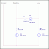
Days back, electricity wiring (that came from a transformer and that) which connects to our building was cut under the road. There was some work that going on, the water supply board was carrying it. They dug the road, and cut-off the wiring of our building. Now, they have connected a temporary wire that takes an aerial route. They have interchanged phase and neutral. I found using this: LED's that describe the condition/state of wiring, in spike busters. [Attachment] That works pretty well, it is just arrangement of wires inside, with no any electronic chip.
I think we need to have some discussion on it's working.

Another ques - intention of this thread, My room's tube light keeps blinks continuously, even it is switched off. I can see this blink only in the dark(Night). I read this, which says:
PHP:
Blinking of tube lights is an indication of bad wiring in your house. The wiring has been reversed entirely in relative positions of live(phase) and neutral. You can test it using your small electric tester. Test the electricity in any 3 pin socket - you will observe that the either left of right (of yourself) will show the presence of electric current. If the current is present in right part of socket, the circuitry is proper, if you find the left portion shows the LIVE current, your home circuitry is wrong.
So, i grasped that it was cause of interchanging the phase and neutral. How does it happen like that? Why does that happen?
 

Attachments

  • AutoPowerStatus.jpg
    AutoPowerStatus.jpg
    35.2 KB · Views: 625
disconnect the neutral line to the tube-light, and see if the bulb glows in the dark.

Make sure you switch of the mains supply to the house first before opening up the wiring....
 
OK there Electroenthusiast attached is the general design of a basic AC line voltage tester for single phase AC as it would come into a home or residence. Remember that Ground and Neutral should be tied together at the source. Look at the image and tell me how it works. :)

Hard as it is to believe it does sound very much like the line (hot) and neutral are reversed. Where do you live? A mistake like that, if true can have real bad consequences on the residents of the building. I would be getting the utility company out there right now before you have a toasted tenant.

Ron
 

Attachments

  • AC Line Test.gif
    AC Line Test.gif
    8.1 KB · Views: 1,643
Why it happens? The back reflector of the tube is grounded. It helps start the lamp. when it's removed, the lamp MAY not start.

Have the problem taken care of ASAP. Don't wait.
 
Yea there would have been a lot of smoke if they actually switched the hot & the neutral! Even if you are in the states (split phase hots), and they lifted the neutral only, you would get the same smoke! That would essentially put all the loads in series across the hots.
 
disconnect the neutral line to the tube-light, and see if the bulb glows in the dark.
Make sure you switch of the mains supply to the house first before opening up the wiring....

You mean the current neutral wire(actual/previously line), i suppose it would stop glowing.

OK there Electroenthusiast attached is the general design of a basic AC line voltage tester for single phase AC as it would come into a home or residence. Remember that Ground and Neutral should be tied together at the source. Look at the image and tell me how it works. :)....toasted tenant.
Ron

Thanks Ron, i'm gonna look into the problem. It's been 4/5 Days, and their task is not yet finished. Perhaps, i need to go and tell them to reverse the temp wiring.
Why it happens? The back reflector of the tube is gro..................Have the problem taken care of ASAP. Don't wait.
Can you please elaborate?
Yes, Thanks. I'm gonna get that fixed soon.


Yea there would have been a lot of smoke if they actually switched the hot & the neutral! Even if you are in the states (split phase hots), and they lifted the neutral only, you would get the same smoke! That would essentially put all the loads in series across the hots.

Just Kidding...Cigar Smoke? LOL, i'm stupid enough to not understand you.
 
OK there Electroenthusiast attached is the general design of a basic AC line voltage tester for single phase AC as it would come into a home or residence. Remember that Ground and Neutral should be tied together at the source. Look at the image and tell me how it works. :)
Ron

;) Thanks Ron, that image tell's it all. But the have used a simple LED here, in my spike buster.
Source/Drain/Gate of FETs, if i'm right?? I'm gonna work on it and will be back.
 
As a simple example, take a neon bulb. How much it ionizes the gas is dependent on distance.

A floerescent lamp emits UV from a little bit of mercury gas in the tube. This excites the phosphor and makes a white light source. Starters, which are obsolete now heated filaments in the ends to make the excitation easier.

A lamp is controlled by a ballast which is basicaally a sloppy transformer that ends up having a high open circuit voltage and a rather fixed short circuit current. It takes a large spike of voltage to kick in the lamp and a smaller voltage to maintain it. The principle of Plasma displays says that you always excite with voltage X which is enough to sustain a cell of light, but not enough to create one.

Real time intensity measurements is far from constant.

That large voltage spike id essentially applied isolated from the ballast, but there is an ionization path to ground (tube to the reflector) which helps start the lamp.
 
;) Thanks Ron, that image tell's it all. But the have used a simple LED here, in my spike buster.
Source/Drain/Gate of FETs, if i'm right?? I'm gonna work on it and will be back.

Yes, many "spike busters", surge protectors or whatever you choose to call then use a single LED. They basically come down to one of the three version I posted. The idea is to look at the circuit I posted and figure out which lamps illuminate under which conditions. :)

Ron
 
Fix it as soon as possible.
Got it fixed.
@Ron
Okay Ron, I'll figure that out. But, what seems to me is: LED's glow only when excited from one side. Need to use a Dual sided LED for this. To confirm, whats abbreviation of DS1,DS2,DS3.

That large voltage spike id essentially applied isolated from the ballast, but there is an ionization path to ground (tube to the reflector) which helps start the lamp.

I didn't understand this part of the explanation.
 
Last edited:
In the three light example of an AC line tester I used Neon lamps with series resistors. Attached is an image of a basic typical neon lamp. The lamps have two elements and will fire or glow on AC or DC. When DC is applied only the Negative element will glow. When AC is applied both elements alternate glowing so both look to be illuminated. Lamps like this were used in AC line testers long before the LED was ever around. :)

Think of them as a small incandescent lamp as far as a voltage detector goes.

Ron
 

Attachments

  • NE2 Lamp.jpg
    NE2 Lamp.jpg
    9.8 KB · Views: 368
  • neon lamps.png
    neon lamps.png
    38.7 KB · Views: 390
Nice Ron, I understood that. But, what if i need to use a LED in the place of Neon Lamps?
Image **broken link removed** shows the symbol for Neon Lamp, but what symbol is that (in your image) for?[so that i can know]
 
The symbol I used was from an Orcad library as I happen to have done the drawing using Orcad Capture. I just used the part as was without editing it or making a fresh part for the library. Actually if you Google Neon Lamp Symbol you will see a few variations, the one you posted being pretty common.

As to using LEDs? I have seen a few circuit testers that actually incorporate small transformers but for the better part units like this are permanent fixtures in line systems. LEDs can be mains powered with a little effort, I suggest you read this link and search these forums as the question of mains powered LEDs comes up quite often around here. Given a choice I would use neon lamps like NE2 if I were to build a line tester simply because neon bulbs, like LEDs last a very long time. Each branch only requires a NE2 bulb and resistor therefore very inexpensive and easy to build.

Ron
 
You can't replace the 3 neons with LEDs unless you add a lot of circuitry to translate the line voltage to LED levels and current requirements (you need a power supply, where will you plug that in when you are not sure the source is safe?).
GB Electrical Inc (and others) make testers (theirs is a GRT-500), basically containing what is shown in post 3, for less than US$20. A tool that should be mandatory for anyone messing with the AC line! E
 
Electroenthusiest:

If you take a Neon lamp and expose it to a high enough electric field, you don't need contact for the lamp to light. The ability to light will depend on the ionization potential of the gas, the breakdown of the gas and the area that the electric field is applied to.

In a florescent lamp, or at least the older ones, there are filiments on either side. Generally these were used for starting by providing a stream of electrons. That stream will flow through the tube, but they will also be attracted to the grounded reflector.

All I'm saying is that the grounded reflector can HELP start the lamp. It's not essential. Longer lamps will be more affected.
 
I don't see why you want to make one especially when a commercial one cost $3.00. Eclipse 400-029 Outlet Tester - Standard Outlets

Another version of this tester incorporates a button for a GFCI test. I glued a small bubble level to the tester and i use it to test and level the outlets when they are installed or replaced.

I have an IDEAL Suretest for comprehensive testing.

See Eclipse 400-029 Outlet Tester - Standard Outlets

I picked it up broken on ebay for about $20. No cables or case.
 
There is a discussion here Fluorescent lamp - Wikipedia, the free encyclopedia about the requirement of a grounded reflector for rapid-start lamps under starting.

There is also a discussion about blinking.
But where? I didnt find anything about blinking(as in this case) there. underlined are the topics that i've still unable to understand.
 
Status
Not open for further replies.

Latest threads

Back
Top