Continue to Site

Welcome to our site!

Electro Tech is an online community (with over 170,000 members) who enjoy talking about and building electronic circuits, projects and gadgets. To participate you need to register. Registration is free. Click here to register now.

  • Welcome to our site! Electro Tech is an online community (with over 170,000 members) who enjoy talking about and building electronic circuits, projects and gadgets. To participate you need to register. Registration is free. Click here to register now.

Reverse polarity switch hooked to timer switch -help for novice

Status
Not open for further replies.

kickboxingfool

New Member
I know this is probably very basic, so I apologize up front for my lack of knowledge. I am planning on building a small sliding door (for a chicken coop) that will be moved up and down via use of a power antenna attached to the door.

When power is applied to the antenna, the door will open. When the polarity is reversed and power applied again, the door will close.

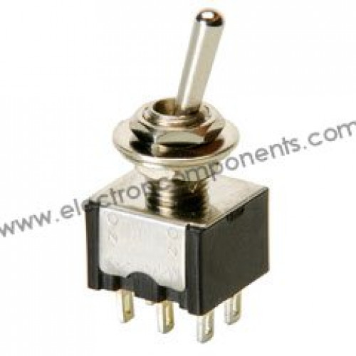
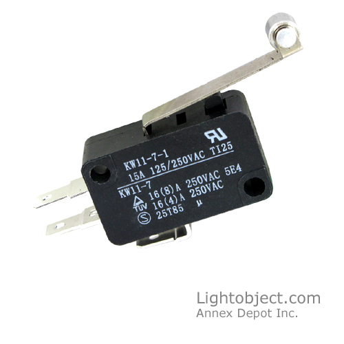
I need the ability to incorporate a contact switch that cuts the power to the antenna when the door is fully closed and another one that does the same when the door is fully open. I also need to be able to automatically reverse the polarity applied to the antenna after each open and close sequence.

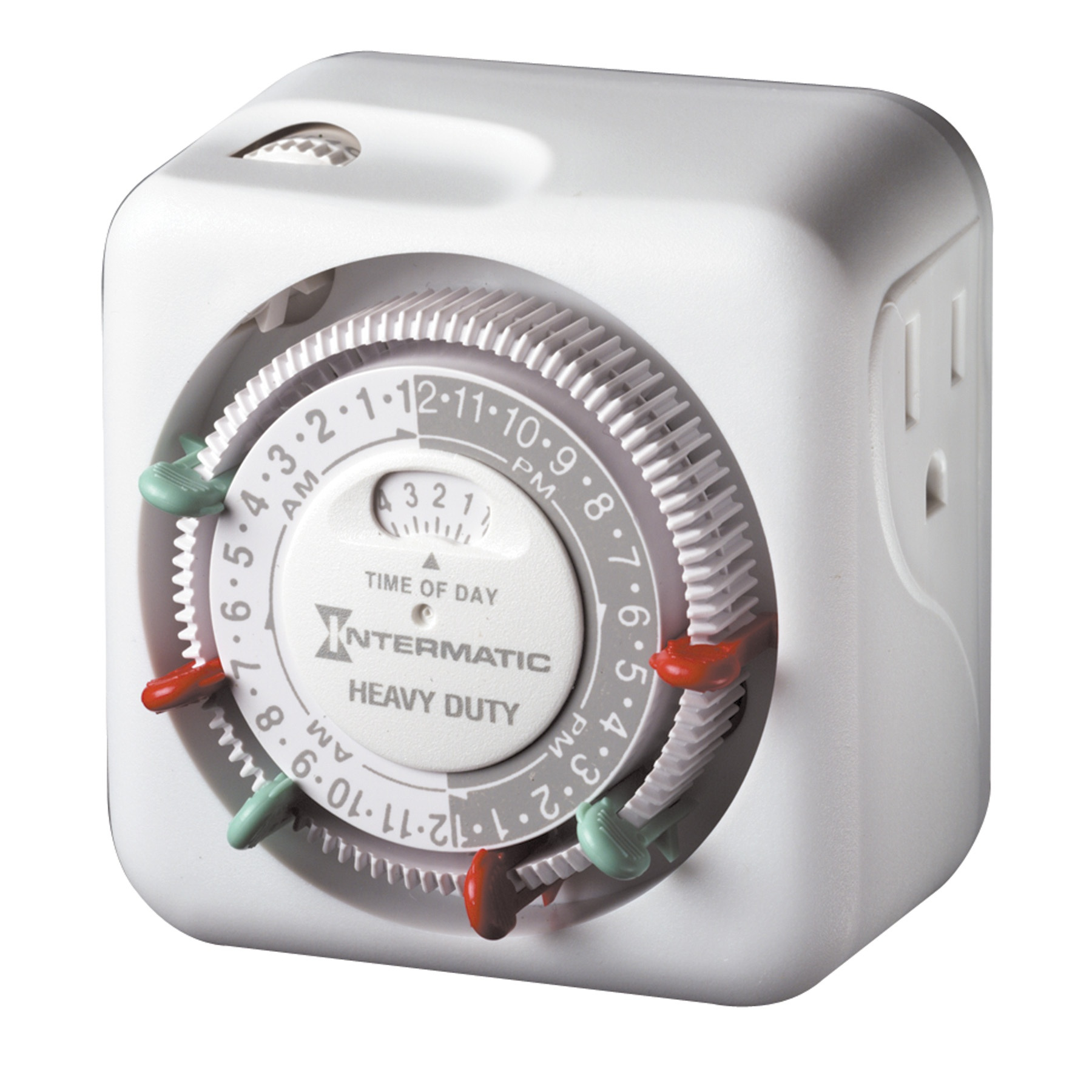
Finally, I need to be able to activate the open/close function via a digital timer so I can change the open and close times as needed throughout the year –unfortunately it will not be based on light and dark or I’d just use a photocell (although the close time will be roughly 1 hour after dark).

I intend to use a 12V transformer to step-down from a 110V output and then run the 12v line out to the coop. A battery back up would be nice, but I have no idea how to pull that off. For now this is more for convenience so I'll just rely on our home power. The open/close function would always be checked morning and night regardless - in other words I would never rely on it for unattended periods of time.

Anyway, I’m an electronics novice, so any help/pointers would be really appreciated. Thanks!
 
You could use a 12 volt DPDT relays for controlling the power antenna. Its easier than you thing for reversing the polarity. Just play with the relays and eventually you will figure it out.
For stopping the door you could use these again you can play around with these and figure it out.
For the timers, you local electronics shop may have some, just hook it up with the relay.
 
I know this is probably very basic, so I apologize up front for my lack of knowledge.

Hy kick,

Welcome to ETO and no need to apologise for lack of knowledge- if everyone did that we would be apologizing all the time.

I am planning on building a small sliding door (for a chicken coop) that will be moved up and down via use of a power antenna attached to the door.

Now I have to appologise for lack of knowledge; can you explain exactly the nature of your 'power antenna'.

Your application sounds quite straight forward. As in many control systems there are two broad approaches: relative and absolute. Relative is normally simpler to implement but absolute is far better in all other aspects, so I am asking about your antenna signal because that is key to the approach that can be used.

There is no reason that I can see why the coup end of things can't be battery powered. The very simplest would be say 3 6550 LiIon batteries which would need charging from time to time. As a phase two upgrade, solar powered automatic charging could be incorporated.

Can you say a bit more about your skills with regard to building electronic units. Would you be able to assemble a small strip-board circuit, with through-hole components into a sealed cast zinc box for example. Can you do basic metal work: drilling, filing, sawing etc
 
Last edited:
I hope you can read the schematic.
S1, switch 1, is a Double Pole Double Terminal type
S2, S3 are Normal Closed limit switches. (normally they are closed and current flows)
Switch 1 connects the battery(+) to the top of the motor. and Battery(-) goes to the bottom of motor.
If you flip the switch the other way, Battery(-) goes to the top of the switch.
The limit switches must be on the right end of travel. They cut off the power in only one direction.
upload_2016-1-14_7-27-44.png


EC_SW_DPDT_toggle-500x500.jpg


LimitSWC2.jpg

Normally closed!! not normally open!
----edit----
A light timer, could turn on a relay, (DPDT) that will replace the Up/Down switch.
**broken link removed**
TN311C_prod_300-1.jpg
 
Last edited:
Here is a solid state version of the motor driver section of the coup door controller. I have the whole circuit sketched to use the radio link but I need the answer to my questions above to finalise.

The circuit will only use any significant power when the motor is moving the door, so the batteries can be permanently connected and can be charged in situ.

At the remote station pressing a button will open the door and pressing another button will close the door. Other arrangements can be provided if specified.

I am thinking about hall effect switches, or similar for the door home sensors as these are more reliable when exposed to weather etc and do not suffer oxide build up with the low currents switched (gold plated switch contacts would help alleviate this problem but not completely).

The four power MOSFETs are £1 UK each and the other parts, not including sealed box and batteries, would be covered by around £5 UK at a guess. The batteries would probably be around £2 UK each and the box would probably be another £5 UK.

ETO_2016_01_14_Iss02-00_COUP_DOOR_CONTROLLER.png

ERRATA

(1) R8 should be shown connected directly to Q19 gate
 
Last edited:
Here is a variation of something from another thread. An impulse relay is an electromechanical, non-volatile toggle flipflop. The contacts remain making contact after the coil impulse has ended, and stay in contact until the next impulse moves the armature to the other state.

ak
MotorReverseLimitSW-1-c.gif
 

Attachments

  • MotorReverseLimitSW-1-c.pdf
    12 KB · Views: 353
Since you didn't put in a location when you registered for the web site we dont know what your AC line voltage is???

12V DC powered timers with sufficient accuracy are expensive, and hard to come by. This uses a standard AC-powered wall clock timer. Assuming you are in the USA or CAN, if you can run 120Vac out to the coop, here is what I recommend. This means an extension cord out to the coop.

Parts list and wiring diagram attached. Note that you can usually find a 12Vdc 2A to 3A wall-wart type of power supply at Habitat for Humanity thrift stores for a couple of bucks... I have seen the wall-clock timers there, too.

Note that the DC power supply must always be powered, the relay is pulled in while the coop door is open.
 

Attachments

  • ChickCoop.pdf
    232.9 KB · Views: 358
Last edited:
AK's idea in post 7 could be used with a time switch If the time switch controls the total power to the circuit then it could be set to come on fo r say 2 minutes at the time when it is required to open and 2 minutes when it is required to close. This does have a problem if the mains is not reliable as if there is a power loss during the 2 minute period then the open / close sequence will become reversed. I use this method to open and close curtains (The mains it fairly reliable here in the UK.) The hardware is different. I use a PIC to control it. The code writes a bit in EEPROM that sets weather the curtains open or close next time power is applied. Also I do not use limit switches. I sense the motor current and when its rises above a set value it switches off the motors. There is also a timer in the code that stops the motors if the over current detection did not work. this has been in use for about 10 years.
 
Thanks for the info everyone! I am blown away by all of the help! - I apologize for the delay in replying, I was working two jobs the last few days. I couldn't see a way to post a reply to each separate post, so I'll just answer your questions one at a time..

Spec - the power antenna is a simple car radio antenna that I will use to physically raise and lower the door, not as a receiver for a wireless signal. I had a connector welded to the end of the antenna to attach it to the coop door. It already has a toggle switch for telescoping the antenna in and out. As far as skills with electronic circuit building - no problem. I'm quite competent with all of the things you mentioned. I'm unclear what you mean by a 'hall effect switch' - if it is more weather-proof, I'm all for it –can you elaborate? You mentioned buttons, but I will be using some type of automatic timer to activate it rather than a manual switch, but even then the timer will only be actively 'on' for around a minute so I think if I incorporate a solar trickle charger, I could use batteries no problem.

Ronsimpson - thanks for the drawings and details. I understand the idea of the DPDT switch, I just can't figure out how to cut the power to the antenna at the end of each sequence (using the NC single pole switches at each end of the doors run) and then have power available on the next sequence . Maybe it's simpler than I realize. For instance, using your circuit identifiers ... Let's start with the door open (it will be a vertical moving door). I apply a current to A and B of the DPDT switch, allowing the power to the antenna to travel from T1 and T2 through connector 1 and 3. The antenna will telescope out and when the door is fully closed it will engage the NC single pole switch and cut the power. When it's time for the door to open, that NC switch is still in the open position... wait, that's okay, because the DPDT switch will be toggled to the other circuit anyway and the whole thing starts over, duh, I get it now.

Analogkid - I like the idea of impulse relays. I'll have to look at them closer.

MikeMI - I live in Idaho, USA. Thanks for the various useful links. I could probably just use a 110v AC timer to activate a relay for the 12v power supply.

Les Jones - I agree, I will probably use a 110v timer. I realize that using the mains is not as reliable, but it would be checked daily. This is simply a convenience set up. Thanks for the post. I have 2 questions for you - 1. You said, "I use a PIC to control it." What is a PIC? 2. You said, "Also I do not use limit switches. I sense the motor current and when its rises above a set value it switches off the motors. There is also a timer in the code that stops the motors if the over current detection did not work. this has been in use for about 10 years." This interests me, could you elaborate?
 
Spec - the power antenna is a simple car radio antenna that I will use to physically raise and lower the door, not as a receiver for a wireless signal. I had a connector welded to the end of the antenna to attach it to the coop door. It already has a toggle switch for telescoping the antenna in and out. As far as skills with electronic circuit building - no problem. I'm quite competent with all of the things you mentioned. I'm unclear what you mean by a 'hall effect switch' - if it is more weather-proof, I'm all for it –can you elaborate? You mentioned buttons, but I will be using some type of automatic timer to activate it rather than a manual switch, but even then the timer will only be actively 'on' for around a minute so I think if I incorporate a solar trickle charger, I could use batteries no problem.

Hi kick,

Many thanks for your clear and concise reply- if only every reply were that good, things would be more interesting for us on ETO.

Seems like I got a bit too fancy with the antenna bit. I was imagining remote control over a wireless link. :joyful:

Glad to hear that you are one of the gang and can do mechanical and electronic things.

Hall effect switches work on the principle that certain semiconductors conductivity is affected by magnetic fields, so the sensor may have a high resistance when out of a magnetic field but a low resistance when in a magnetic field. Hall effect sensors are generally considered to be the most suitable for harsh environments because they are immune to dirt, moisture vibration etc. Also they have no moving parts. For this reason they are used on cars (autos) for sensing functions, like ABS sensors in the wheel hub, for example. There is another technology that this used more often these days, magneto-resistance, but the principle is the same. In fact you could probably use a couple of ABS sensors from a scrap car, but it would probably be better to buy new. I don't think they are very expensive, but haven't checked.

The arrangement for your application would be two tiny magnets fixed to the coup door and two hall effect sensors fixed to the door frame. The position of the magnets and sensors would be such that the magnet would be near to the sensor when the door is in the required position, either open or closed. The hall effect sensors have two wires each that connect to the coup door controller, as I call it.

Don't concern yourself with the controls that operate the door: any form of control that you like, within reason, would be possible. I just used the two buttons as a simple example. Timer control would be OK. Rather than using an electro-mechanical timer, an all-electronic timer would be possible. I don't have the information in my head though, so a bit of research would be required

Can you clarify a point for me? I am not sure what your setup is. I had imagined that you had the coup in your garden and that you wanted to control the coup door from your house some distance away.

Another thing that we will need to know quite soon is the current that the antenna motor takes when it is opening the coup door. If you could provide two readings that would be ideal:

(1) Normal door operation current

(2) Current when you are applying reasonable force to resist the movement of the door (be careful not to damage anything though)
 
Last edited:
Hi,
This is the schematic uf the curtain controller. It controls a pair of curtains so you can remove quite a few components and some of the code.

CurtainSch.jpg

The PIC 16C84 was old when I built the unit but I had some in stock so I thought this was a good way to use one of them. I would suggest using a more modern PIC such as a PIC16F628 or PIC16F88 Ignore the comment on the schematic"To allow in circuit programming" The LM339 (You could use an LM393) comparator compares the voltage across the current sense resistors with the preset voltage from the potentiometers
I have seen code listings inserted by others but I have not found how to do this. I will try to find how to do this and add the listing. I have attached the source file but I don't know if you will be able to save it.
curtain05.asm
Les
 

Attachments

  • curtain05.asm
    12.8 KB · Views: 483
Last edited:
Hi KISS,
Thanks for that information.

Here is the code to go with my post #14

Code:
;Curtain controller
; Version 05
;PIC16C84, set for 4.00MHz XTAL, WDT OFF, POR on
;Instruction time at 4MHZ is 1.0 us

;written in MASM

TIMEOUT_VAL   EQU D'45'   ;Timeout value in seconds to stop motors


INDF       EQU 0x00  ;page 0 & 1
TMR0       EQU 0x01  ;0
OPTION_REG    EQU 0x01  ;1
PCL       EQU 0x02  ;0 & 1
STATUS      EQU 0x03  ;0 & 1
FSR       EQU 0x04  ;0 & 1
PORTA      EQU 0x05  ;0
TRISA      EQU 0x05  ;1
PORTB      EQU 0x06  ;0
TRISB      EQU 0x06  ;1
  ;0x07 not available
EEDATA      EQU 0x08  ;0
EECON1      EQU 0x08  ;1
EEADR      EQU 0x09  ;0
EECON2      EQU 0x09  ;1
PCLATH      EQU 0x0A  ;0 & 1
INTCON      EQU 0x0B  ;0 & 1

STATE_FLAGS    EQU 0x0C
[\code]


delay1       EQU 0x0D  ;Used in delay routine
delay2     EQU 0x0E  ;Used in delay routine
delay3     EQU 0x0F  ;Used in delay routine
timer0     EQU 0x10   ;Used in timout routine
timer1     EQU 0x11   ;Used in timout routine

EEPROM0     EQU   0x00   ;Saves copy of STATE_FLAGS when powered off

;----- STATUS Bits --------------------------------------------------------

IRP  EQU  H'0007'
RP1  EQU  H'0006'
RP0  EQU  H'0005'
NOT_TO  EQU  H'0004'
NOT_PD  EQU  H'0003'
Z  EQU  H'0002'
DC  EQU  H'0001'
C  EQU  H'0000'
;----- INTCON Bits --------------------------------------------------------

GIE  EQU  H'0007'
EEIE  EQU  H'0006'
T0IE  EQU  H'0005'
INTE  EQU  H'0004'
RBIE  EQU  H'0003'
T0IF  EQU  H'0002'
INTF  EQU  H'0001'
RBIF  EQU  H'0000'

;----- OPTION Bits --------------------------------------------------------

NOT_RBPU  EQU  H'0007'
INTEDG  EQU  H'0006'
T0CS  EQU  H'0005'
T0SE  EQU  H'0004'
PSA  EQU  H'0003'
PS2  EQU  H'0002'
PS1  EQU  H'0001'
PS0  EQU  H'0000'

;----- EECON1 Bits --------------------------------------------------------

EEIF  EQU  H'0004'
WRERR  EQU  H'0003'
WREN  EQU  H'0002'
WR  EQU  H'0001'
RD  EQU  H'0000'

;==========================================================================
;
;I/O Pin useage

;   RA0     Output   Right close
;   RA1     Output   Right open
;   RA2     Output   Left  close
;   RA3     Output   Left  open
;   RA4/TOCK1   Input
;
;   RB0/INT     Input
;   RB1     Input
;   RB2     Input
;   RB3     Input
;   RB4     Input   Jumper to ground To control power on action.  Off - move at power on. On no action at power on.
;   RB5     Input   Push button (Active low)
;   RB6     Input   Right current limit
;   RB7     Input   Left current limit
;
;STATE_FLAGS bit useage
;
;   Bit0     Right closing
;   Bit1     Right opening
;   Bit2     Left closing
;   Bit3     Left opening
;   Bit4     Last direction - set for closing
;   Bit5
;   Bit6
;   Bit7


; define reset and interrupt vector start addresses

   org   0       ; start at address 0000h
   goto   INIT     ; normal service routines from Reset vector
   org  4     ; interrupt vector 0004h, start interrupt routine here
   goto   INIT     ; interrupt  (Should not get here as interrupts not used.)

; **********************************************************************************************


;   Initialize
;
  ORG 0x0005     ;Start of program memory


     DE  "V05 03/04/06"
;
INIT  BCF INTCON,GIE      ;turn off global interrupts
  BTFSC INTCON,GIE    ;Confirm global interrupts off
  goto INIT

   BSF    STATUS,5   ;Select register bank 1
  movlw   B'11111111'
  movwf   TRISB     ;Configure port B0-B7 as input
  movlw   B'00010000'
  movwf   TRISA     ;Port A0-A3 as output , A4 as input
;

  movlw   B'00000100'    ;timer ratio 1:32 (1/100sec). Pull-up Rs on (bit7=0)
  movwf   OPTION_REG

   BCF   STATUS,5   ;Select register bank 0


   clrf   PORTA     ;Set initial state with motors stopped
   movlw   EEPROM0     ;EEPROM address
   call   EEREAD
   movwf   STATE_FLAGS
;
   movlw   D'100'     ;Delay for 1 second
   call   Wait10ms


;         ---------------------
; Test jumper for powerup action
;
     movfw  PORTB
   andlw   0x10     ;Test for jumper present (Bit 4)
     btfss  STATUS, Z
   goto   MA04


;Main loop

MAIN
     movfw  PORTB
   andlw   0x20     ;Test for push button to be released
     btfsc  STATUS, Z
   goto   MAIN     ;Loop waiting for button to be released   
;
MA01     movfw  PORTB
   andlw   0x20     ;Test for push button to be pressed
     btfss  STATUS, Z
   goto   MA01     ;Loop waiting for button to be pressed
   call   DELAY
MA02     movfw  PORTB
   andlw   0x20     ;Test for push button still pressed (de-bounce)
     btfss  STATUS, Z
   goto   MA01     ;False press go back to wait loop
;
MA03
     movfw  PORTB
   andlw   0x20     ;Test for push button to be released
     btfsc  STATUS, Z
   goto   MA03     ;Loop waiting for button to be released   

MA04
   btfsc   STATE_FLAGS,4   ;set if last direction was closing
   goto   MA05
   call   CLOSE
   goto   MAIN
MA05   call   OPEN
   goto   MAIN
;
;
;   ---------------------------------------------------------------------------------------
;
;     SUBROUTINES FROM HERE
;
CLOSE
   movlw   TIMEOUT_VAL
   movwf   timer1
   movlw   D'100'     ;Value for timer0 to reach zero in 1 second
   movwf   timer0

   movlw   0x05     ;Bits 0 & 2
   movwf   PORTA     ;Set both motors to close
   movlw   0x15     ;Bits 0, 2, 4
   movwf   STATE_FLAGS

   movlw   EEPROM0     ;EEPROM address
   movwf   EEADR
   movfw   STATE_FLAGS
   call   EWRITE   

CLOSE01
   call   TESTBUTTON   ;"Z" set if button pressed
     btfsc  STATUS, Z
   goto   CLOSE05
   btfss   PORTB,6     ;Test for right current limit
   goto   CLOSE02
   call   DELAY
   btfss   PORTB,6     ;Test for right current limit again
   goto   CLOSE02
   bcf   PORTA,0     ;Stop right motor
   bcf   STATE_FLAGS,0   ;Clear right closing flag

CLOSE02   
   btfss   PORTB,7     ;Test for left current limit
   goto   CLOSE03
   call   DELAY
   btfss   PORTB,7     ;Test for left current limit again
   goto   CLOSE03
   bcf   PORTA,2     ;Stop left motor
   bcf   STATE_FLAGS,2   ;Clear left closing flag

CLOSE03
   movfw   STATE_FLAGS
   andlw   0x05     ;Test to see if neither motor closing flag is set
     btfsc  STATUS, Z   ;If zero then finished closing
   return

CLOSE04
   call   TIMEOUT
     btfss  STATUS, Z   ;If set timeout has occured so stop motors
   goto   CLOSE01

CLOSE05
   bcf   PORTA,0     ;Stop right motor
   bcf   STATE_FLAGS,0   ;Clear right closing flag
   bcf   PORTA,2     ;Stop left motor
   bcf   STATE_FLAGS,2   ;Clear left closing flag
   return

;
;         ---------------------------------
;
OPEN
   movlw   TIMEOUT_VAL
   movwf   timer1
   movlw   D'100'     ;Value for timer0 to reach zero in 1 second
   movwf   timer0

   movlw   0x0A     ;Bits 1 & 3
   movwf   PORTA     ;Set both motors to open
   movlw   0x0A     ;Bits 1 & 3
   movwf   STATE_FLAGS

   movlw   EEPROM0     ;EEPROM address
   movwf   EEADR
   movfw   STATE_FLAGS
   call   EWRITE   

OPEN01
   call   TESTBUTTON   ;"Z" set if button pressed (7 Cycles if button not pressed)
     btfsc  STATUS, Z
   goto   OPEN05
   btfss   PORTB,6     ;Test for right current limit
   goto   OPEN02
   call   DELAY
   btfss   PORTB,6     ;Test for right current limit again
   goto   OPEN02
   bcf   PORTA,1     ;Stop right motor
   bcf   STATE_FLAGS,1   ;Clear right opening flag

OPEN02   
   btfss   PORTB,7     ;Test for left current limit
   goto   OPEN03
   call   DELAY
   btfss   PORTB,7     ;Test for left current limit again
   goto   OPEN03
   bcf   PORTA,3     ;Stop left motor
   bcf   STATE_FLAGS,3   ;Clear left opening flag

OPEN03
   movfw   STATE_FLAGS
   andlw   0x0A     ;Test to see if neither motor closing flag is set
     btfsc  STATUS, Z   ;If zero then finished opening
   return
OPEN04

   call   TIMEOUT
   btfss  STATUS, Z   ;If set timeout has occured so stop motors
   goto   OPEN01


OPEN05
   bcf   PORTA,1     ;Stop right motor
   bcf   STATE_FLAGS,1   ;Clear right opening flag
   bcf   PORTA,3     ;Stop left motor
   bcf   STATE_FLAGS,3   ;Clear left opening flag
   return

;
;         ---------------------------------
;*****************************************************************************   
;
;  Function : Test for button press and debounce ("0" for pressed)
;  If button pressed "Z" flag will be set   
;
;  Input:  None
;Time 6 cycles if button not pressed
;*****************************************************************************   
TESTBUTTON
TB01     movfw  PORTB
   andlw   0x20     ;Test for push button to be pressed
     btfss  STATUS, Z
   goto   TB03     ;No button pressed - return
   call   DELAY
TB02     movfw  PORTB
   andlw   0x20     ;Test for push button still pressed (de-bounce)
TB03   return
;*****************************************************************************   


DELAY         ;Delay for 100 Ms
   movlw   D'10'
   call   Wait10ms

;*****************************************************************************   
;
;  Function : Wait100us
;  delays for a multiple of 100us
;
;  Input:  multiple in W
;
;*****************************************************************************   
Wait100us
  movwf  delay2

d1us002
  movlw  D'33'      ;1 Cycle   
  movwf  delay1       ;1 Cycle   
   
d1us001   
  decfsz  delay1, F     ;1 cycle , 2 on skip   
  goto  d1us001      ;2 cycles   
  decfsz  delay2, F
  goto  d1us002
  return   


;*****************************************************************************   
;
;  Function : Wait10ms
;  delays for a multiple of 10ms
;
;  Input:  multiple in W
;
;*****************************************************************************   
Wait10ms
  movwf  delay3
   
d1ms001
  movlw  D'100'
  call  Wait100us
  decfsz  delay3, F
  goto  d1ms001
  return


;*****************************************************************************   


;*****************************************************************************   
;
;  Function : TIMEOUT
;       Stops motors if limit not reached in preset time   
;     If timeout reached "Z" flag set
;  Input:  None
;
;*****************************************************************************   
;
TIMEOUT
   movlw   0x01
   call   Wait10ms
     decfsz   timer0
   goto   TO1
   movlw   D'100'     ;Value for timer0 to reach zero in 1 second
   movwf   timer0
   movfw   timer0     ;This instruction makes sure the "Z" flag is clear
     decfsz   timer1   
   return
   clrw       ;Set the "Z" flag
   return

TO1   movfw   timer0     ;This instruction makes sure the "Z" flag is clear
   return

;*****************************************************************************   
;
; subroutine to read from EEPROM
;
;  Function : EEREAD         
;     
;  Input:  EEPROM address to read from  (In "W" register)
;
;  Output:  Date read from EEPROM  (In "W" register)
;
;*****************************************************************************  
; subroutine to read EEPROM memory

EEREAD   movwf    EEADR     ; indirect special function register
   bsf    STATUS,RP0   ; select memory bank 1
   bsf   EECON1,RD   ; read EEPROM
RD_RD   nop
   btfsc   EECON1,RD   ; skip if RD low (read complete)
   goto    RD_RD     ; wait for low RD (read RD)   
   bcf   STATUS,RP0   ; select bank 0
   movf   EEDATA,w   ; EEPROM value in w
   return
   
;*****************************************************************************   
;
; subroutine to write to EEPROM
;
;  Function : EWRITE
;       Writes data in "W" register to internal EEPROM
;     Address oe EEPROM to be written must first be put in EEADR register   
;     
;  Input:  Value to write to internal EEPROM
;
;*****************************************************************************   

; subroutine to write to EEPROM

EWRITE   movwf   EEDATA     ; data register
   bcf   INTCON,GIE   ; disable interrupts
   bsf   STATUS,RP0   ; select bank 1
   bsf   EECON1,WREN   ; enable write
   movlw   0x55     ; place 55H in w for write sequence
   movwf    EECON2      ; write 55H to EECON2
   movlw    0xAA     ; AAH to w
   movwf   EECON2     ; write AA to EECON2
   bsf   EECON1,WR   ; set WR bit and begin write sequence
   bcf   EECON1,WREN   ; clear WREN bit
WRITE   btfsc   EECON1,WR   ; skip if write complete WR=0 when write complete
   goto    WRITE     ; not written yet
   bcf   EECON1,EEIF   ; clear write interrupt flag
   bcf   STATUS,RP0   ; select bank 0
;   bsf   INTCON,GIE   ; enable interrupts     ;Not required as interrupts not used
   return

;*****************************************************************************


  END     ;final line. This line must be retained.

Les.
 
Spec - to answer your questions...
I am not sure what your setup is. I had imagined that you had the coup in your garden and that you wanted to control the coup door from your house some distance away.
The chicken coop is about 10 ft away from the corner of my house. I can either run the house electrical to it, or simply use a 12VDC single (or dual) battery set up with a solar trickle charger (my choice). The battery(s) I've been testing with are 7A units from my son's electric scooter. I want the door to be completely automatic with no interaction on my part. I will have the door open at first light (approximately) and then close about 30 mins after dark (so all of the chickens are in). As the daylight times change, I will adjust the timers accordingly. Since it does not need to be exact, I will only need to change the timers 4 or 5 times each year.
If you could provide two readings that would be ideal:

(1) Normal door operation current
(2) Current when you are applying reasonable force to resist the movement of the door (be careful not to damage anything though)
Operating current is 0.5A (+– 0.2A). I haven't yet taken a reading of what the current is when opening the door (lifting the weight of the door). The door is not heavy at all and in preliminary testing the antenna easily lifts weights that are heavier than the door.
__________________________

I am attaching my final circuit drawings. Let me know what you guys think and if I'm missing something obvious. They're quite simple and certainly nothing like Les Jones set up above (he's light years ahead of my abilities). Thanks! --Andrew (kickboxingfool)
 

Attachments

  • Chicken door reversing polarity circuit.pdf
    56.5 KB · Views: 298
Last edited:
Les:

If you use "code=asm" it does more pretty printing. Here's SOME of your code with that tag.

Code:
;Curtain controller
; Version 05
;PIC16C84, set for 4.00MHz XTAL, WDT OFF, POR on
;Instruction time at 4MHZ is 1.0 us

;written in MASM

TIMEOUT_VAL   EQU D'45'   ;Timeout value in seconds to stop motors


INDF       EQU 0x00  ;page 0 & 1
TMR0       EQU 0x01  ;0
OPTION_REG    EQU 0x01  ;1
PCL       EQU 0x02  ;0 & 1
STATUS      EQU 0x03  ;0 & 1
FSR       EQU 0x04  ;0 & 1
PORTA      EQU 0x05  ;0
TRISA      EQU 0x05  ;1
PORTB      EQU 0x06  ;0
 
Not sure why you need two timers. I showed how to do it with a single timer, but the relay stays pulled in for either all day, or all night, which would not be ideal if you are going to power it on solar.
 
Status
Not open for further replies.

Latest threads

New Articles From Microcontroller Tips

Back
Top