Continue to Site

Welcome to our site!

Electro Tech is an online community (with over 170,000 members) who enjoy talking about and building electronic circuits, projects and gadgets. To participate you need to register. Registration is free. Click here to register now.

  • Welcome to our site! Electro Tech is an online community (with over 170,000 members) who enjoy talking about and building electronic circuits, projects and gadgets. To participate you need to register. Registration is free. Click here to register now.

resonance circuit and voltage divider

Status
Not open for further replies.

spectrum

Member
hi all,

(sorry, circuit is in a second step edited for corrections)

https://www.electro-tech-online.com/attachments/diagram-png.16724/

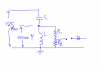
i have the circuit as attached, there is an antenna (coil) that transmit a 125Khz carrier, in resonance conditions. The signal have 200Vpp amplitude on the coil. It is a serial resonance circuit.

My need is to have a voltage Vpp near 2,5V as Vout, without cousing problems to the antenna, and i'm really wandering how to calculate this values for R1 and R2. Then i will need to rectify the wave, and give a pulse positive wave to an op amp.

C is about 160pF and L(antenna) have a 12 ohm resistance measured, and should have 4.05 mH as value.

I just need an help about how to proceed, don't need no calculations or circuits done. Just would like to learn with some help what is difficult to learn from the books.

Many Thanks, angelo
 

Attachments

  • diagram.png
    diagram.png
    3.7 KB · Views: 687
Last edited:
The resistors will be in parallel with the tuned circuit and will reduce its Q. Then the output voltage across the tuned circuit will be reduced.

Tap the coil or use two capacitors in series replacing the one capacitor as a capacitive voltage divider.
 
Hi Spectrum,

audioguru said:
The resistors will be in parallel with the tuned circuit
and will reduce its Q. Then the output voltage across the tuned circuit
will be reduced.

Tap the coil or use two capacitors in series replacing the one capacitor
as a capacitive voltage divider.

I hate to say this but I agree with Audioguru.
You could move the inductor to the hot side and the capacitor to the
ground side and split it up to make a capacitive divider.
A second solution could be an inductive coupled link round the inductor.
By doing so you'll get a transformer.

on1aag.
 
ok, many thanks for the nice idea, i can do the capacitor splitting, but i've put for test the 2 resistors at the COIL sides, as in the last corrected diagram attached, and the circuit go on to transmit and receive fine.

I've put for now a R1of 6,8M and R2 of 10M, and i have about 3Vpp on R2. The big problem of this is that i didn't unsdertand why that values give me the 3Vpp.

Btw, if you thing the capacitor voltage divider is better, i sure use that strategy.

thanks
angelo
 
Now your tuned circuit is series-resonant. Before it was parallel-resonant.
R2 as part of a voltage divider is loaded down with the rectifier's filter capacitor or the opamp circuit or something.
 
spectrum said:
ok, many thanks for the nice idea, i can do the capacitor splitting, but i've put for test the 2 resistors at the COIL sides, as in the last corrected diagram attached, and the circuit go on to transmit and receive fine.

I've put for now a R1of 6,8M and R2 of 10M, and i have about 3Vpp on R2. The big problem of this is that i didn't unsdertand why that values give me the 3Vpp.

Btw, if you thing the capacitor voltage divider is better, i sure use that strategy.

thanks
angelo

Your values for R1 and R2 are extremely high resistance so it is likely that the meter that you use (scope?) is also lowering the net value of R2 and so reducing the measured voltage. You should consider lowering those resistances to, perhaps, 68K and 100K ohms. Your detector cannot operate from such high source resistance in any case, so perhaps even lower values will be necessary. That is why it is more efficient to use "autotransformer" technique of tapping the coil or using two capacitors to tap the load into the resonant circuit.
 
Hi Spectrum,

The 6M8 load won't make much difference.

spectrum said:
I've put for now a R1 of 6,8M and R2 of 10M, and i have about 3Vpp on R2. The big problem of this is that i didn't understand why that values give me the 3Vpp.

The reason why you measure 3 Vpp across the 10 M resistor is that
you connected a 100k load parallel to it. :D

on1aag.
 
Status
Not open for further replies.

Latest threads

Back
Top