Hi all -
Currently designing a resistive network with two 12Vdc supplies used to bias either a JFET or MOSFET (both N type). Essentially I need to be able to bias each device in several different ways, so the it is likely that some of the resistors will be replaced by potentiometers (namely, one of the resistors in the voltage divider and probably the resistor(s) on the source (possibly drain as well) node of the device. I might also just swap out entire resistors if it turns out I don't need too many different biasing levels.
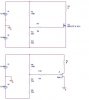
anyway, schematics below.
the 1 meg resistor is to provide a high impedance node to the gate.
I have little (no) experience with JFETs, but it seems that the only major difference for biasing is that the gate needs to be below the source voltage for it to turn on. So, does it seem like these circuits will work for MOSFET and JFET biasing, if connected as shown? I'm trying to keep the circuit as similar as possible between the two, so I can swap out one device for another making as few changes as possible.
thanks!
EDIT: forgot to mention, i want to bias mostly in the saturation region. this looks close to accomplishing it.
im currently trying to simulate the circuit. does anyone know how to do a sweep of a resistor value, rather than a voltage sweep?
Currently designing a resistive network with two 12Vdc supplies used to bias either a JFET or MOSFET (both N type). Essentially I need to be able to bias each device in several different ways, so the it is likely that some of the resistors will be replaced by potentiometers (namely, one of the resistors in the voltage divider and probably the resistor(s) on the source (possibly drain as well) node of the device. I might also just swap out entire resistors if it turns out I don't need too many different biasing levels.
anyway, schematics below.
the 1 meg resistor is to provide a high impedance node to the gate.
I have little (no) experience with JFETs, but it seems that the only major difference for biasing is that the gate needs to be below the source voltage for it to turn on. So, does it seem like these circuits will work for MOSFET and JFET biasing, if connected as shown? I'm trying to keep the circuit as similar as possible between the two, so I can swap out one device for another making as few changes as possible.
thanks!
EDIT: forgot to mention, i want to bias mostly in the saturation region. this looks close to accomplishing it.
im currently trying to simulate the circuit. does anyone know how to do a sweep of a resistor value, rather than a voltage sweep?
Attachments
Last edited:
