FZ750Horse
New Member
Hello, I'm new to this site and hoping for some advice re. voltage regulation on a motorcycle alternator. I'll keep this as concise as possible but there is quite a lot of info to share...
The bike is a 1987 Yamaha FZ750, heavily modified for race use, and the alternator is a Nippon Denso ND3 (photo attached); I think it was made as a special for Yamaha. It is 3 phase and has field coils rather than fixed magnets. The regulator/rectifier (photos attached) is bolted to the end of the alternator and designed to supply charging current at 14.8V - 15.3V, which it does.
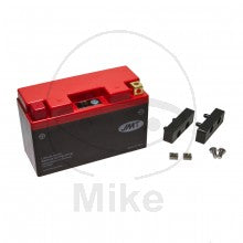
My problem is that for weight and space reasons I want to use a LiPo battery (photo attached) which will tolerate an absolute maximum charging voltage of 14.8V. In use the battery is less than 2" from the rider's primary reproductive organs so I'm keen to get this right...
It looks to me as if the rectification is being done on the coil winding side and the regulation on the brush side (photo)? Unless there are components in the resin casting (unlikely) I'm assuming that the whole regulator circuit is contained in the round can mounted on the brush side.
So... Is there a package similar to the OE one which will drop the charging voltage by 0.5V, or a little more? the battery drain is tiny so the charging rate doesn't need to be optimal. If there's nothing available 'off the shelf' could someone suggest a circuit I could build to achieve the required charging voltage.
Thanks for reading.


