Continue to Site

Welcome to our site!

Electro Tech is an online community (with over 170,000 members) who enjoy talking about and building electronic circuits, projects and gadgets. To participate you need to register. Registration is free. Click here to register now.

  • Welcome to our site! Electro Tech is an online community (with over 170,000 members) who enjoy talking about and building electronic circuits, projects and gadgets. To participate you need to register. Registration is free. Click here to register now.

Automotive Generator Universal Digital Voltage Regulator

Status
Not open for further replies.

CK3

Member
Hello everyone,

I've spun this off from the thread "Automotive 6 Volt Generator Transistor Voltage Regulator." I've been inspired by Danwvw and also herbie1200 on TheSamba (see Homemade solid state 6V regulator and Solid state 6 volt regulator ) to try my hand at designing and building a voltage regulator for my '64 Karmann Ghia, possibly usable for other applications. I want to use a microcontroller to make the regulator programmable and allow for some optimization of the regulator's characteristic curve.

This is an open source project.

What follows are the requirements I've come up with. I'd welcome any comments or advice. I mentioned in the other thread that I work with microcontrollers. I probably should also mention that I am the "software guy" in our little operation. When I get into the design, I'm really going to need help on the analog/power stuff.

Problem Statement
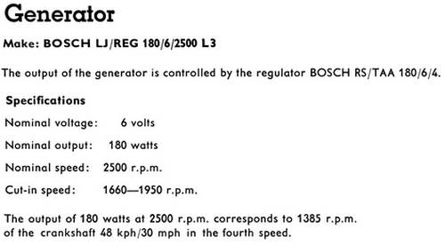
Produce a drop-in replacement for the BOSCH 7V 45A generator voltage regulator commonly used on early VW engines. The replacement should optimize charging while keeping the generator and battery within recommended parameters. The regulator should be configurable for either ordinary lead-acid battery or AGM battery (e.g., Optima), and possibly 6, 8, or 12 volt battery. It would be nice to maintain the original external appearance. It should cost less than $100 to build (including the cost of any special tools needed).

External Interfaces
Here is a diagram of the original regulator in my car:
BbD8j8aoEl7O63y4KOMnjaaNUhvZ7kVF-LtQDd07q98dbYOvvGUdLsJeAmL0G9u7hyWTuJQtOVO6BMBOJAsbLuM3Q6vHTaxW9qwfmx9lhv5ONqx2Vr674RZTavHSEgRLd7zBg_xB
There are 4 electrical interfaces to the regulator:
  1. B+/Terminal 51: direct connection to car battery
  2. D-/Ground: generator armature winding negative and chassis ground
  3. D+/Terminal 61: generator armature winding positive and warning light
  4. DF: generator field winding
Definitions of Terms
  • Cut-out: B+, the connection to the battery, is open circuited
  • Cut-in Voltage: When the regulator is in cut-out state and the generator voltage is increasing, this is the voltage at which the regulator makes a connection between B+ of the regulator and D+ of the generator. From there the charging current can flow to the battery or into the electrical system.
  • Cut-out Voltage: When the regulator is in cut-in state and generator voltage is decreasing, this is the voltage at which the regulator breaks the connection between B+ of the regulator and D+ of the generator. This prevents the battery from discharging through the generator. (This was a tunable parameter for the original regulator, but will probably not be used in my design.)
  • Regulating Voltage: The voltage at which the regulator prevents any further rise in voltage
  • Regulating Current: The current at which the regulator prevents any further increase in current
  • Idiot Light: generator and cooling warning lamp on the car's dashboard (in the speedometer):
1601357090420.png

Theory of Operation
  • When conditions are right, the regulator connects the D+/Terminal 61 (generator armature winding) to B+/Terminal 51 (direct connection to car battery) to allow the generator to charge the battery and supply current to the car.
  • The regulator adjusts the generator field current (through D+/Terminal 61) to control the generator’s output voltage. It must limit the output voltage according to the specifications of the battery and the car’s electrical system.
  • The regulator must limit the power produced to avoid overloading the generator. It can do this by reducing the output voltage when current is high, or by maintaining a constant voltage up to a preset current limit at which it cuts out.
  • The original BOSCH two-unit regulator, consisting of a cut-out relay and a compensated voltage regulator relay, limits voltage such that the higher the current, the lower the voltage supplied by the generator. This protects the generator against overloading. This characteristic of the regulator can be seen in the following graph:
    wasJE3sW8D1TFCEbBaMd6gzvC4M0up4e-qxOiLt9O_axnjMl--wKpvOZ3A0WEXmlOcU1wQ5pgaH5PeFBM-5SGjksx9g4dX8TkIlpoAYhkF_FZO8yKT-F4ruQAq1x2oH-mFFzJMCZ
  • BOSCH (and others) also made three-unit regulators, consisting of a cut-out relay, a voltage regulator relay, and a current relay. These have a step-function characteristic; constant voltage up to a cutoff at a fixed current.
  • I’m proposing an optimized regulator that maintains a constant voltage as current rises up to a fixed power limit. Beyond that point, voltage begins to fall as current continues to rise, in order to maintain a constant power.
BYHcUazvdkeB7By3Xdivir29rEzi0M_a47piWaBpSSlcna9Yhin28KyaFZGpHBETos1lxJTOB5LnFffnJj5d0kTVHprdxHAJY-RM-OC0v22NaYfJoyYOvJ4MIApv78-iKDTwrvWO
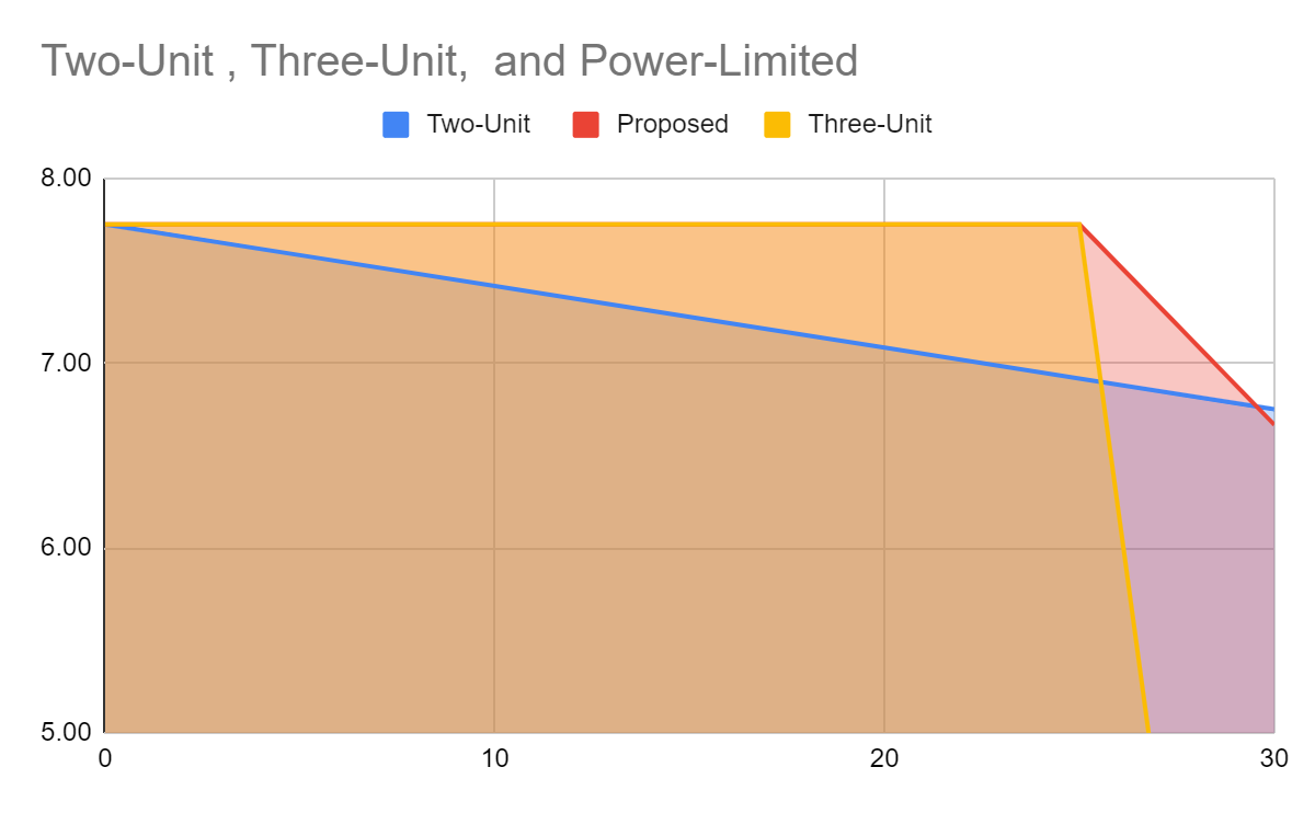
Taking the Two-unit TA regulator curve (above) for example, the regulator is limiting this generator to roughly 30A x 6.75V = ~200 Watts load. But, if you back up to 15A it is capped to 7.25V which is only ~109 watts. Why not stay at 7.75V x 15A = 116 watts? It could stay at 7.75V until 200W/7.75V = ~26A, and then drop off steeply to stay in a 200W envelope. From 26A, it would drop at a slope of
(6.75 - 7.75) / (30 - 26) = -1 V / 4A
This scheme would allow it to keep going up to higher current until the voltage is low enough that current to the battery naturally levels off.
Requirements
  • Voltage & Current regulation: this needs to be configurable. For example, from 1965:
LCbz4RkyzXFg-LwIY5it5tIjGU69gYeaTWfxTFURlw8kRcw7XvjnpX6XNYt7xtaCRnsx3QgVprfkRn67AIyu13p042NmMptNUm9Ipq1BQjFJjL3qxSJU6xDh-oe8J7hgSaf3aw6E
    • Over the years VWs had 6/7V generators that were 90, 160, 180 watts, at least. And then a variety of 12/14V generators. Regulators were originally matched to generators.
    • It would be nice to have a universal design that could be configured for 6V, 8V, or 12V battery (standard lead acid, or Absorbent Glass Mat [AGM]) and a specified generator wattage.
      • I think specifying battery charging voltage range and generator wattage rating should be sufficient to characterize the regulator.
    • Limit voltage and current in such a way as to optimize ampere-hour input to the battery in a given time.
  • Cut-in: Optima specifies "Recommended charging information: Alternator: 6.65 to 7.5 volts, no amperage limit." for the REDTOP battery. So, for this example, I think the cut-in voltage should be 6.65.
  • Regulating Voltage: Once cut-in, limit voltage to the top of the recommended charging voltage range; e.g., 7.5 volts for the Optima. As current increases and reaches the point where the product of the voltage and current is equal to the generator power limit, begin reducing voltage stay within the power limit.
  • Cut-out: When cut-in, as generator speed decreases and output voltage falls, the regulator should monitor the current to the B+ terminal and cut-out when flow is no longer positive. There probably also needs to be some hard voltage limit, in case there is a short or something. There probably should also be some hard limit on current.
  • User interface:
    • Dashboard idiot light (incandescent, original equipment):
      • Steady on: no generator output
      • Slow flash: low battery voltage
      • Fast flash: over voltage or over current (or over heat?)
    • Configuration interface: This needs some thought. The prototype, at least, will have a USB port to connect a terminal. Other ideas: a pushbutton and an LED or LCD on the regulator (under the cover?)? DIP switches?
Startup Conditions
  • Normal
    • Turning the key on puts battery voltage on the other end of the (incandescent) idiot light connected to D+/Terminal 61. The regulator senses this non-zero voltage and powers up from B+/Terminal 51.
    • When the ignition key is on, but the generator is not turning, idiot light glows.
    • Once generator is producing a detectable voltage, idiot light is turned off.
    • The regulator initially grounds DF (generator field winding) to demand maximum voltage from the generator.
  • Dead battery
    • Is it reasonable to require at least a little bit of battery power; just enough to power up the MCU through a buck/boost circuit?
    • Trying to run off the generator alone, no battery, would be difficult.
    • Maybe add a little rechargeable lithium backup battery?
Running Conditions
  • When the generator starts turning fast enough to produce at least the Cut-in Voltage, the regulator cuts in and connects D+/Terminal 61 to B+/Terminal 51.
  • The regulator remains cut in as long as there is a positive current flow from the generator to the battery, unless the voltage drops to something abnormally low.
  • Once cut in, the regulator rapidly switches DF on and off to regulate the generated voltage and current, as described above.
Shutdown Conditions
  • When the key is switched off, D+/Terminal 61 is no longer powered on the other side of the bulb. The regulator senses this and powers down.
  • When the regulator is powered down, it must be cut out.
Failure Conditions
  • Broken fan belt: the generator stops turning, the current reverses and the regulator cuts out. The regulator senses 0 voltage on D+/Terminal 61 and lights the idiot light steadily.
  • Low battery voltage: the regulator senses abnormally low voltage on B+/Terminal 51 and slow flashes the idiot light.
  • High battery voltage: the regulator senses abnormally high voltage on B+/Terminal 51 and fast flashes the idiot light.
  • Short circuit: the regulator senses high current and low voltage on B+/Terminal 51 and fast flashes the idiot light, and maybe cuts out?
  • Open circuit? Sense no/low current on B+/Terminal 51?
  • High temperature?
Competitive Analysis
There are a few solid state regulators available on the market:

It’s hard to know what’s inside these. Datasheets would be nice, but I haven’t found any.

Did I miss anything?

-Carl
 
Last edited:
That looks mostly OK to me.

A few points:
The D+ to battery connection will likely be via a high current schottky diode, so there is nothing to connect/disconnect; if the dynamo is producing sufficient voltage, it will be charging the battery (at a current controlled by the field power).

I'd suggest a hall-effect current sensor rather than using a shunt resistor for current; that minimises voltage drops and heat productions.

The initial or dead battery start up only needs a FET to hold the field terminal to ground. That could be an auxiliary device driven directly from an MCU pin, too slow for PWM but not needing any external gate driver to work.
[Or even from a micropower charge pump, powered from the diode sense circuit below & the FET clamped off by the MCU once that is running].

I came up with a warning light sense/control circuit for Dan's regulator, though I can't remember offhand if he used it:
From the warning light terminal, a resistor, eg. 470 Ohms, feeding two 1N4000 diodes in series to ground.
A 1K resistor across the diodes.

A PNP bipolar transistor across the 470R, with emitter to warning light terminal & 470R base-emitter.

The diode to resistor / transistor junction will switch to 1.2V or so when the ignition is on, which can be used to turn on another bipolar transistor via a resistor. That can be the initial "power on" switch control.

Grounding the base of the transistor across the lamp resistor via another 470R resistor & NPN transistor should switch on the warning light without affecting the sense voltage.


Allow plenty of power & sense wiring protection for the MCU, plus a large flywheel diode for the field output!
Cars are electrically an extremely noisy environment, especially when switching high current inductive loads.
 
rjenkinsgb: Thanks for those excellent suggestions!

The D+ to battery connection will likely be via a high current schottky diode, so there is nothing to connect/disconnect; if the dynamo is producing sufficient voltage, it will be charging the battery (at a current controlled by the field power).

Apparently one of the commercial solid state regulators (Clover Systems) uses an "ideal diode". Quoting herbie1200:
If I remember clover description they use:
- a HALL sensor to control generator current
- an "ideal diode", to emulate cut off contacts. A normal diode drops 0,7 volts, that at 30A are 21Watt; a schottky diode drops ~0.2 volts (6-7watt); an ideal diode drops 0,0..volts, so remains almost cold
(See Solid state 6 volt regulator.)

I looked into ideal diodes a little, and I thought maybe I could get the same benefits (and more flexibility) using the MCU to control a MOSFET (or HEXFET or something?).
 
Last edited:
I think the "ideal diode" may be a schottky diode bridged by a suitable FET when the dynamo is generating appropriate power?
That seems the most practical approach.
 
I think the "ideal diode" may be a schottky diode bridged by a suitable FET when the dynamo is generating appropriate power?
That seems the most practical approach.
I was looking at these:
MAX16141 3.5V to 36V Ideal Diode Controller with Voltage and Current Circuit Breaker - Maxim Integrated
MAX16915 Ideal Diode, Reverse-Battery, and Overvoltage Protection Switch/Limiter Controllers with External MOSFETs - Maxim Integrated

herbie1200 doesn't seem to like the idea:
Against the ideal diode consider also that generator output is very "dirty", a lot of positive and negative peaks generated by the commutator itself (it rotates twice engine speed and has lot of pole to commutate foreach turn) and the inductive nature of the whole electric machine. Spikes are not well tollerate by MOS devices.

Schottky diode drops only 0,2V, considering that the 6V generator is capable of an output of almost 18V unregulaated, the diode voltage drop can be not an issue.
 
The only reason as I see it is to reduce heat dissipation. at 30A, the diode would be dissipating quite a bit of heat.
Even a large schottky diode will drop a significant voltage at high current, I don't know where they got 0.2V from?

0.5 - 0.7V is more realistic at high load, which means 20W or more heat at full output.
An example high-current schottky diode; see the voltage vs current chart on page 3:

I do not see any reason to use a separate controller, a bypass FET (or relay) can simply be controlled by the MCU & switched on anytime current flow is from the dynamo to the battery at above some threshold, or off otherwise.

However, it's a "bells and whistles" feature that does not affect the rest of the basic regulator functions.
 
Thanks, rjenkinsgb.

Here are the two "reference implementations" that I have found:

herbie1200:
1601736480970.png


Danwvw:
1601736763805.png

Both use diodes for the cutout.

For the field current switch it looks like Danwvw is using a MTP75N05 (MTP75N05HD?) and herbie1200 is using IRL3915 (IRLR3915?) Could I switch one of those directly with a pin from a 3.3v MCU, or would I need some kind of amplifier on that? Would either one of those be appropriate for a cut-out switch (if I went with that instead of a diode)?

However, it's a "bells and whistles" feature that does not affect the rest of the basic regulator functions.
Yes, I agree. For the first iteration, I'll use a diode, to keep things simple. It looks like herbie1200 is using an SBL4045PT and Danwvw is using dual 4015s (MBR4015CTLG?) Any reason to prefer one over the other?
 
Here is a sketch of a high level design:
Voltage Regulator HLD (4).png

Here are the subsystems:
  • Microcontroller (MCU): Something along the lines of STM32G431KB Mainstream Arm Cortex-M4 core with DSP and FPU, 170MHz with 128Kbytes of Flash memory, Math Accelerator, Medium Analog level integration and various comm Interfaces including USB FS 2.0 , USB Type-C and Power Delivery, CAN-FD (Datasheet)
  • D+ voltage (generator armature output) measurement: Whatever conditioning is needed to interface to Analog Digital Converter (ADC). Also, see Generator charging warning light; they are on the same terminal.
  • Generator charging warning light control: rjenkinsgb came up with a warning light sense/control circuit that can switch on the warning light without affecting the sense voltage. The illumination of the bulb will be under control of the MCU.
  • B+ (connection to battery) current measurement: Could be a shunt or a Hall-effect current sensor, and whatever conditioning is required to interface to ADC.
  • B+ voltage measurement (optional): to ADC [for warning light only] (same as D+ when cut-in). This is a "bells & whistles" item for things like flashing the warning light when battery voltage is low.
  • Cut-out: This makes or breaks the connection between the generator armature and the battery, primarily to allow current to flow from the generator to the battery, but not vice versa.. Could be a diode or a big MOSFET switch under control of the MCU. A high current Schottky diode would be simplest for the first iteration, and might be the most robust in the face of noise and spikes. A FET would enable some interesting scenarios like cut-out for failure conditions.
  • Regulator switch: Digital GPIO controlled DF to D- switch [big MOSFET] that controls the generator field current.
  • MCU power supply: derived from B+, enabled by Terminal 61 high indicating key switched on [Should this also support batteryless operation? rjenkinsgb: "The initial or dead battery start up only needs a FET to hold the field terminal to ground."]
  • User Interface: Some way to configure the voltage regulator. Set parameters such as voltage limit, power limit, current limit. Could take the form of a USB port for connection to a laptop, or it could be something like an LED or two, or even a little LCD, and a pushbutton or two.. With a USB port the options are wide open for things like monitoring and diagnostics, as well as configuration.
My plan is to flesh out the design of each subsystem, one at a time, and then put it all together into a schematic.
 
Last edited:
That looks good.

Something like this would be OK for the main current sense; they are available in different ratings:
**broken link removed**

The voltage sense circuits need nothing more than a resistive divider with a filter cap and a schottky diode from the ADC pin to MCU power.

Personally, I'd use a mid-range PIC as the controller; they have all the facilities needed and you can get a PCB made at JLCPCB, with a surface mount PIC ready assembled (along with any other surface mount parts).
We've just had some boards made using a PIC18F26K80:

Whichever MCU you use, I'd add a precision voltage reference (2.5V ?) so the ADC readings are consistent rather than being proportional to the device supply voltage.

The MCU should be able to run from a 3.3V low drop out automotive rated voltage regulator, with some filtering caps.
 
I know someone who would be in the market for a completed one.

The control does not need to be fast by electronic standards. I noticed the 5 Msps on the ADC converter, and I realise that is what it is capable off, and you wouldn't necessarily use that speed. The only control that you have is on the generator field winding, and its inductance prevents fast changes of current and therefore fast changes in field.

The alternator on modern cars rely on the battery for short-term stability, and there's no point trying to get faster control that what works fine.

I suppose the cut-out needs to be fast in case of a fault, but I would suggest a fuse anyhow as any bit of electronics could go short.

On that, fusing the dynamo connection would also be a good idea as they aren't inherently current limiting like alternators.

A Schottky diode could get very hot if that is the only cut-out you have. It would dissipate about 20 W which is a lot for a small box like that. Also underbonnet temperatures can be very high and difficult to predict, and hot Schottky diodes appear as a dead short, so with the engine off, you could get reverse current flowing through the diode, and the diode staying hot due to the current, which would almost certainly end badly.

Actually, having a local temperature sensor in the control box so that it shuts down and lights the warning light would be a good idea. However, with the warning light connected between the dynamo output and the battery, with no field current and high engine speed, the dynamo might generate enough voltage that the voltage remaining across the warning light won't illuminate it.
 
I wasn't aware that some PIC's had two though?
I'd guess it's to give options for 5V or 3.3V supplies, in that case?

The DSPIC33EP ones we use in some gear do not have an internal references; I've not used any other new types in quite a while, until this PIC18 project - which does not use the ADCs, so I never looked at that part of the data.
 
Although I cannot provide any more meaningful advice over that which has already been provided, I would still like to congratulate you on providing a very well written problem statement.

This in contrast with the ubiquitous but lazy questions one likely encounters: “I would like to build a 2 kW pure sinewave inverter. I have a pair of 741 and several 2N3055. How should I connect them?”

EDIT; My father also had a ‘64 VW Karmann Ghia. It was s fun little car.
 
...

Whichever MCU you use, I'd add a precision voltage reference (2.5V ?) so the ADC readings are consistent rather than being proportional to the device supply voltage.
...
Excellent point. I have added it to the original post.
 
...
The control does not need to be fast by electronic standards. I noticed the 5 Msps on the ADC converter, and I realise that is what it is capable off, and you wouldn't necessarily use that speed. The only control that you have is on the generator field winding, and its inductance prevents fast changes of current and therefore fast changes in field.
I realize that the STM32G431KB that I've been looking at is an "embarrassment of riches", so to speak, but for $5.50 in quantity 1 from Mouser, and available temperature rating to 130C (but maybe not for $5.50), why not? And the little development board looks nice, for $12.51. I happen to be working on another project (for most of the past year) that uses a different MCU with Cortex M4+M0, so I am biased (although there is also a PIC18F in the box).

I suppose the cut-out needs to be fast in case of a fault, but I would suggest a fuse anyhow as any bit of electronics could go short.

On that, fusing the dynamo connection would also be a good idea as they aren't inherently current limiting like alternators.
I think a fuse or two is a good idea. herbie1200 said he put a 30A fuse in his, and it has never blown, with a supposed 45A generator.

A Schottky diode could get very hot if that is the only cut-out you have. It would dissipate about 20 W which is a lot for a small box like that. Also underbonnet temperatures can be very high and difficult to predict, and hot Schottky diodes appear as a dead short, so with the engine off, you could get reverse current flowing through the diode, and the diode staying hot due to the current, which would almost certainly end badly.
Yes, that's one reason I was thinking of a MOSFET. I think they can get down to low forward drops. Then there's also the "ideal diode", which seems to use a sort of FET inside.

Actually, having a local temperature sensor in the control box so that it shuts down and lights the warning light would be a good idea. However, with the warning light connected between the dynamo output and the battery, with no field current and high engine speed, the dynamo might generate enough voltage that the voltage remaining across the warning light won't illuminate it.
I agree that a temperature sensor would be great to have. I think some MCUs have something built it. Re: the warning light: maybe I could toggle Terminal 61 between ground and B+ to flash the light; with luck that would work one way or the other. With bad luck, though, I suppose that even with no field current D+ might provide enough current to smoke something that tried to ground it.
 
Status
Not open for further replies.

Latest threads

New Articles From Microcontroller Tips

Back
Top