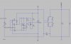
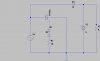
All that sounds like fun but i don't think my xt 500 has a self regulating coil. i have blown 4 bulbs in a week and a half and they are hard to find now 25 years later. for the moment i have a very crude regulator that stops my battery boiling. a triac shorts the coil triggered by two zener diode in series anode together. my scope tells me it works a bit but it is too crude.
no body has better ideas?
scr are used in industry regulators but i have no idea how to use them in a shunt circuit.
i would like to ride my motorbike after dark and sleep at night.
no body has better ideas?
scr are used in industry regulators but i have no idea how to use them in a shunt circuit.
i would like to ride my motorbike after dark and sleep at night.
Attachments
Last edited: