Continue to Site

Welcome to our site!

Electro Tech is an online community (with over 170,000 members) who enjoy talking about and building electronic circuits, projects and gadgets. To participate you need to register. Registration is free. Click here to register now.

  • Welcome to our site! Electro Tech is an online community (with over 170,000 members) who enjoy talking about and building electronic circuits, projects and gadgets. To participate you need to register. Registration is free. Click here to register now.

Ramped LED Strobe

Status
Not open for further replies.

EdStraker

Member
I have constructed a variety of "strobe" circuits in the past using Transistors and 555's but never both. Since I've been on a circuit binge lately I thought I might as well post this problem too.

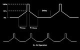
Concept is a modified Sine Wave to have a low glow LED slowly ramp up to 50%-70% brightness and then "spike" or "flash" at peak brightness then ramp back down to minimum glow again. But, have adjustable timing and 50-50 adj ramp time also. I have attached a graphical interpretation of what I am trying to achieve.

*Correction on schematic 0% should have been 10%
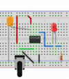
 

Attachments

  • ramp_strobe.jpg
    ramp_strobe.jpg
    103.2 KB · Views: 209
Last edited:
The sine reference ?

You want independent timing and V over -

1) Trampup width time
2) Trampdown width time
3) Tbright pulse width
4) Vglow to Vbright transition V
5) Tglow V before ramp starts
6) Period/frequency

Is that accurate description ? Independent controls over each of these ?

What do you mean by 50-50 adj ramp time ?


Regards, Dana.
 
Didn't need ramp up and ramp down to be independently controlled. Both the same i.e. 1 sec. up, 1 sec down. Bright pulse is not too critical but the equal ramp up and down times need to be the same length but adjustable. If that makes sense.
 
Try a basic 555 oscillator using the timing resistor (pot + fixed) between output and the capacitor, rather than pin 7 for discharge.
That gives you a symmetrical "sawtooth with rate control by a single pot.

Add a high impedance buffer, eg. an emitter follower (darlington?) from the timing cap, to feed the LED. That should give the gradual brightness up / down change.

Add a comparator with the inputs from the timing capacitor and the wiper of a pot connected across power. Use the output of that to feed (via a resistor) the base of a PNP transistor that has emitter to positive and the collector to the emitter of the other transistor, that feeds the LED.

By adjusting the second pot, you should be able to adjust the point that the comparator switches and forces the LED to maximum brightness.


The steady ramp up/down and bright flash is like the effect from a rotating beacon, from a single point of view - is that what you are creating?

Just for info, I did a design for someone else on here last year, to drive multiple LEDS in a circle & emulating a full rotating beacon - if you fancy playing with PIC mcus?
 
Here is a first pass cut at problem, again using mBlock and a Arduino Nano board.

The delay between rampdown and rampup, is that fixed, and width of 100% brightness also,
is that fixed ?

1630327899416.png


1630328935749.png


Note also I used two pwms, inside part, one to control brightness, the other to create a DAC for the scope capture shot above.

Ignore fuzz on scope capture waveform, thats just a limited RC filter used to effect the DAC from the PWM output. I just did
not use large enough values to remove the clock noise coming out of PWM.

So all you would need is the board, LED, and a R. If you did it with ATTINY85 just the chip and LED and R and Cap to bypass
the ATTINY85 power pin. TINY solution less accurate timing than board unless you added a xtal (board has xtal).

When I did the jump to full brightness I did it from 50% to 100%, I think 25% to 100% looks better.

This is roughly solution would look like if you used the ATTINY85 -

1630351873474.png


Nano Board I think better because programming is simpler, and has accurate timekeeping.

1630353267005.png


Regards, Dana.
 

Attachments

  • 1630327822989.png
    1630327822989.png
    233.2 KB · Views: 203
  • 1630351773111.png
    1630351773111.png
    134.2 KB · Views: 205
Last edited:
You can reuse the 'raindrop' circuit from your other post. Just replace the 8 LEDS with 1 and adjust the resistor values:

https://tinyurl.com/yesarm7m

1630349005294.png

Adjust the timer frequency to define the ramp times and the resistors to adjust the steps.

You could throw a capacitor in to smooth it if you don't like the discrete steps and a couple more to stretch the off and peak on dwell times.
You could even daisy chain a couple of SIPOs if you needed finer granularity.
 
Last edited:
Status
Not open for further replies.

New Articles From Microcontroller Tips

Back
Top