Roff
Well-Known Member
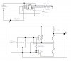
Post detailed schematics of the transmitter and receiver that you are using, with component values.bananasiong said:can anyone help me?
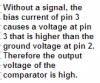
i've tried this circuit, and i connected a LED to the pin 1 of the op-amp and ground to the cathode of the LED. when there is no signal, the LED is high.
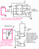
 and it should work in ur case) , the coil will pick the freq. and , if u need connect it to pin 2
