Continue to Site

Welcome to our site!

Electro Tech is an online community (with over 170,000 members) who enjoy talking about and building electronic circuits, projects and gadgets. To participate you need to register. Registration is free. Click here to register now.

  • Welcome to our site! Electro Tech is an online community (with over 170,000 members) who enjoy talking about and building electronic circuits, projects and gadgets. To participate you need to register. Registration is free. Click here to register now.

Ques about power mosfet internal diode

Status
Not open for further replies.

agent420

New Member
As I understand it, most power mosfets include an internal reverse biased clamping diode. Does this internal diode adequately protect the device when switching an inductive load, ie a relay or solenoid?

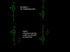
I can't quite decipher the answer to this question from the datasheets, but I did find this pdf from Micrel that states "No clamp diode is necessary since the MOSFET performs this task, but safe operating area (SOA) and the additonal dissapation should not be forgotten" on page 2. Following that is a diagram of a solenoid controller using an IRF530 without a discrete clamping diode.

I have several IRF530 mosfets I want to use for relay and solenoid controllers. By right or wrong habit I have always included reverse biased clamping diodes with any switched inductive load, but I grew up using BJT devices and mosfets are relatively new to my designs.

Could someone shed some light on this subject for me?

Thanks!
 
The reverse diode is not very fast, and I never trust them to clamp any inductive loads. Using IRF44N's I tried to incorporate the intrinsic diode as a clamp, but generally ended up with random failures until using a separate freewheel clamping diode. Check the IR website for inductive motor circuits, they also suggest separate diodes, and have some great circuit tips also.
 
Hmm... could you perhaps cite a reference or link?

I looked through IR's appnotes, and in the archive section there is AN-967 discussing mosfets in pwm motor and ups designs. While this document refers to an earlier generation of devices (generation III, I think they're up to gen V), it says that the internal freewheeling diodes are capable of protecting the device, and none of the reference designs they illustrate include any external diodes. I can only think that mosfet technology has improved since that was written.

[edit]

I guess a somewhat related question would be, what purpose would be in designing a recovery diode within the device, only to require an additional external one in a popular type of switching circuit? Doesn't make much sense.

[edit 2]

I also wonder in there could be any potential stability issue caused by the emi emitted from the wiring connected to a switched inductive load that does not have a frewheeling diode across it... Could it be that the mosfet is not damaged, but the radiated energy from the leads (like an antenna) disrupt other devices?

I knew I should have gone to EE school ;)
 
Last edited:
OK... **broken link removed** states that the function of the freewheeling diode in an inductive motor circuit is not protection, but rather efficiency. While I thought the diode was for protection, they state an RC snubber circuit is the protection. :confused:
 
I don't have my IR book where I am, but they show that it is still good design practice to use separate devices. I will try and find the AN # later.

The reverse diode, as I understand it, is a "byproduct" if you will of how the MosFET is built. The material creates what is know as a intrinsic body diode.

the diode works great in many slower applications, but a quick snapping inductive load can create a spike of greater magnitude than the body diode can handle. The only design I have that relies on the body diode is a PWM LED lamp controller that is battery operated. If the battery is connected backwards, the body diode conducts, and the LED's turn on steady instead of flashing ( the LED modules have a bridge rectifier built in, so they are not polarity sensitive ) Gives me reverse polarity protection for the power devices for free.

Yes, you can generate all sorts of EMI/RF noise with undamped inductors and the wires carrying the current.
 
Last edited:
That external diode is in the wrong position to provide a free-wheel path IF you are switching an inductive load (say a relay).

No diode needs to exist across the switch. IT needs to be across the Inductor.


Now if such FET's were used in a H-bridge then their intrinsic diode can be used as a free-wheel path. They tend to be slow and are really not match to the main switches characteristic
 
Styx said:
That external diode is in the wrong position to provide a free-wheel path IF you are switching an inductive load (say a relay).
I am more familiar with low-side switching, but it seems to me that the DC Chopper schematic is illustrating high-side switching, and in that case the external diode would be correctly placed? I mean all it has to do is enable reverse current flow through the inductive device, right?

Styx said:
Now if such FET's were used in a H-bridge then their intrinsic diode can be used as a free-wheel path. They tend to be slow and are really not match to the main switches characteristic
This seems to be the general consensus... and not that I disagree, but if that's the case why don't all of the manufacturers app notes and data sheets explicitly say that? I am most confused by the lack of clear, definitive device specs in this regard. For example, the 780x regulator series data sheets suggest that if you have > 1u cap at the output pin for transient filtering, you should include a bypass diode (reverse bias) from the output to input pins to protect the device against damage from reverse current flow. I can't find any such suggestion in manufacturers notes regarding power mosfets. To the contrary, as I pointed out, many of the app notes I have looked at state the opposite.

zevon8 said:
I don't have my IR book where I am, but they show that it is still good design practice to use separate devices. I will try and find the AN # later.

The reverse diode, as I understand it, is a "byproduct" if you will of how the MosFET is built. The material creates what is know as a intrinsic body diode.
I see. I would interested in any relevent app notes you could toss my way.
 
Last edited:
Yes these diodes are slow.But this means it will be slow at thurn off.At thurn on they ware as fast as a general diode you can buy.This is not very good when driving high freq in to a inductive load becuse the diode will keap conducting.This is fixed by puting a scockey over it.

I would go on the shure side and put a didoe anti parallel whith the reley.

mosfets may not be needed for this anyway.Most reley only need a very small curent to switch so a BJT is mostly good enugh
 
agent420 said:
I am more familiar with low-side switching, but it seems to me that the DC Chopper schematic is illustrating high-side switching, and in that case the external diode would be correctly placed? I mean all it has to do is enable reverse current flow through the inductive device, right?

Styx is right. That intrinsic diode is not in the right position to snub out an inductive spike in any arrangement. An inductor (or relay coil) wants to force current to keep flowing in the original direction when the switch goes off, and can make high voltage trying to make that happen. The intrinsic diode, even if it were fast enough, only shorts out current going in the opposite direction through the MOSFET. It will not come into play.

The snubber diode must be across the inductor itself. When the inductor generates its own voltage to force current to flow, it will be the reverse polarity of the normal coil voltage and the diode will short it out properly.
 
agent420 said:
I am more familiar with low-side switching, but it seems to me that the DC Chopper schematic is illustrating high-side switching, and in that case the external diode would be correctly placed? I mean all it has to do is enable reverse current flow through the inductive device, right?
NO!!! it is still in the wrong position, the anti-parallel diode in a FET provides NO free-wheel path for an inductive load IF the cct is a chopper-cct be it high-side OR low-side (see picture)

agent420 said:
This seems to be the general consensus... and not that I disagree, but if that's the case why don't all of the manufacturers app notes and data sheets explicitly say that? I am most confused by the lack of clear, definitive device specs in this regard. For example, the 780x regulator series data sheets suggest that if you have > 1u cap at the output pin for transient filtering, you should include a bypass diode (reverse bias) from the output to input pins to protect the device against damage from reverse current flow. I can't find any such suggestion in manufacturers notes regarding power mosfets. To the contrary, as I pointed out, many of the app notes I have looked at state the opposite.
the info is there, it is just hard to decipher, look at the recovery time of the Diode - THIS is the killer. All the info is there it is just deciphering it.
Anyway the intrinsic diode has more in common with a Zener then a regular diode, would you use a Zener as a free-wheel diode?
FOr low-power stuff (say a couple of 10's of amps) the intrinsic diode (WHICH is useful in a 4-switch H-bridge) the slowness of the intrinsic diode really isn't that much of a concern (unless you switch at silly speeds > 50kHz)
 

Attachments

  • untitled_1.png
    untitled_1.png
    4.5 KB · Views: 269
Last edited:
Got my IR book now, the aplication note is AN-936 , a general guide, but worthy reading, it's called the "do's and don'ts of using power hexfets."

https://www.electro-tech-online.com/custompdfs/2006/06/an-936.pdf

As an aside, way back in the early nineties I was working with one of the IR field engineer reps on a large stepper motor circuit and he gave me a piece of advice that I will always remember:

When driving an inductive load, think of it like a fist fight - you want to get in the first shot, and make it count. Hit'em hard ( provide plenty o' gate current ) or the fight is dragged out longer than you want ( linear operation, things get overheated ) and then be sure to duck, in case it fights back ( provide a separate diode for free-wheeling ).
 
Yes i used a zener as a diode in a flyback driver.It preformed crapy whith a scotkey it also got hot and had a crapy output.Then put in zeners and the output was way better.Then replacd the cap in the timer it hit its resonant freq and the flyback arced over.

So here the diode was taking power from the flyback and thurning it in to heat.In this case we need to let it swing and snub befroe the mosfets zener conducts becuse it would not switch off fast enugh at +20khz

But in a reley its not a problem so you could get a cheap 1 amp diode over it.

Oh and the inductive kickback may cause unexpected behaviour in the rest of the cirucit on the same suply line.
 
Thank you all for your replies. I'll be sure to use the snubber diodes in my designs, they're cheap insurance. Not much of a change for me really, as I said I've always used them with BJT devices anyway.

Not being able to quickly locate definitive information, it was just a little confusing. I am surprised that the datasheets don't emphasize that point more, considering how common that type of circuit is.

Styx said:
NO!!! it is still in the wrong position, the anti-parallel diode in a FET provides NO free-wheel path for an inductive load IF the cct is a chopper-cct be it high-side OR low-side (see picture)
Thanks for the illustration. As soon as I saw it I realized I must have suffered another brain cell loss... I knew that! :eek:
 
Last edited:
FWIW, someone pointed me towards the Motorola IRF530 Datasheet. It states that the integral body diode features a fast recovery time comparable to a discrete external diode, and that "A Power MOSFET designated E-FET can be safely used in switching circuits with unclamped inductive loads" (page 5).
 
agent420 said:
OK... **broken link removed** states that the function of the freewheeling diode in an inductive motor circuit is not protection, but rather efficiency. While I thought the diode was for protection, they state an RC snubber circuit is the protection. :confused:
That's true, but it's only the case for PWM controllers, the diode allows the inductive energy stored in the motor to carry on powering the motor when in between switching cycles. Some higher powered controllers subsitute this diode for a MOSFET which is more efficient because the on resistance is lower.
 
Status
Not open for further replies.

Latest threads

New Articles From Microcontroller Tips

Back
Top