Continue to Site

Welcome to our site!

Electro Tech is an online community (with over 170,000 members) who enjoy talking about and building electronic circuits, projects and gadgets. To participate you need to register. Registration is free. Click here to register now.

  • Welcome to our site! Electro Tech is an online community (with over 170,000 members) who enjoy talking about and building electronic circuits, projects and gadgets. To participate you need to register. Registration is free. Click here to register now.

Query about a DAC based design

Status
Not open for further replies.

tkvenki

New Member
Hi all,

I need an accurate 50Hz AC voltage source.
That can vary from 0 - 5V.

So i was just wondering weather i could do this.
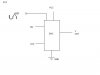
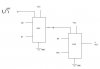
In the diagram attached, i wil be using a micro-controller which will give input to my DAC.

And i will give an AC signal to my Vref of the DAC.
So i will be getting an AC signal at my analog output controlled by the output of the micro-controller.

Will this setup work??
if yes, what are the design constraints?


Thanking you
Venkatesh T.K
 

Attachments

  • untitled_158.jpg
    untitled_158.jpg
    8.4 KB · Views: 702
current replay

hi akg


current is not at all a problem for me , because I am going to give this voltage to a high impedance circuit . is there any problem in having a voltage follower circuit in the output if there is any loading effects. My doubt is that will this circuit be able to produce the ac waveform exactly 50hz ac that I am giving to it.

Thanks for your interest
 
Yes, you can produce an accurate 50Hz sinewave in this way, you should follow the D2A with a buffer and a low pass filter. I would also suggest altering the size of the signal using a digital potentiometer (or something similar) - if you do it before the D2A quality will suffer as you reduce the output level.
 
Re: current replay

tkvenki said:
hi akg
current is not at all a problem for me , because I am going to give this voltage to a high impedance circuit . is there any problem in having a voltage follower circuit in the output if there is any loading effects. My doubt is that will this circuit be able to produce the ac waveform exactly 50hz ac that I am giving to it.
Thanks for your interest

what abt this
sine wav gen (regulated pwr supply,MFR) + buffer + pot:
 
Hi akg,

That will be fine.
But we need some software interfacing for our variable supply,
So i intend to drive the DAC with a controller.

Anyway, can i cascade 2 DAC's to improve the resolution?
I have attached a circuit diagram.
Please correct me if i'm wrong.
 

Attachments

  • dia_194.jpg
    dia_194.jpg
    12.6 KB · Views: 674
tkvenki said:
Hi akg,

That will be fine.
But we need some software interfacing for our variable supply,
So i intend to drive the DAC with a controller.

Anyway, can i cascade 2 DAC's to improve the resolution?
I have attached a circuit diagram.
Please correct me if i'm wrong.
ok..
y don't u use a high res DAC like (16bit)
https://www.alldatasheet.com/datasheet-pdf/pdf/124254/MAXWELL/7846A.html
i don't know the cascading scheme.
 
tkvenki said:
Anyway, can i cascade 2 DAC's to improve the resolution?
I have attached a circuit diagram.
Please correct me if i'm wrong.

No you can't connect them like that, but how much resolution are you needing? (and why?).
 
You need to use a bipolar DAC, which can handle positive and negative reference voltages. Some DACs are unipolar.
 
Ron H said:
You need to use a bipolar DAC, which can handle positive and negative reference voltages. Some DACs are unipolar.

Why do you think that?, the actual requirements have never really been explained, but I haven't managed to 'mind read' that anywhere 8)
 
Nigel Goodwin said:
Ron H said:
You need to use a bipolar DAC, which can handle positive and negative reference voltages. Some DACs are unipolar.

Why do you think that?, the actual requirements have never really been explained, but I haven't managed to 'mind read' that anywhere 8)
From the original post,
And i will give an AC signal to my Vref of the DAC.
He could probably apply a biased sine wave to a unipolar DAC and AC couple the final output, but clipping could be a problem unless he leaves some headroom, which would seem to complicate the design.
 
Ron H said:
He could probably apply a biased sine wave to a unipolar DAC and AC couple the final output, but clipping could be a problem unless he leaves some headroom, which would seem to complicate the design.

But we've no idea what the design is?, or if he requires no DC shift on the signal or not?.

Does "give an AC signal to my Vref of the DAC" make any sense?.
 
I agree that it would be helpful if the OP would post more info about his application. He did say this:
I need an accurate 50Hz AC voltage source.
That can vary from 0 - 5V.
My understanding is that he wants a digitally controlled attenuator for a 50Hz signal. If this is true, then "give an AC signal to my Vref of the DAC" makes sense to me.
 
Tvenki,

Dont cascade your D/A that way. Just choose a converter that has the appropriate resolution that has already been suggested.

Consider the possibility of not using a D/A at all thus avoiding code & controllers. If you need constant adjustment the D/A may be the right way to go but if you are going to set your 50Hz and make one adjustment to it (DC or otherwise) there could be simpler ways that do not require a D/A with all that "overhead"

Can you tell us what you need it for? You'll get better responses.

Also there seems to be some confusion about the nature of your signal.

signals are loosly talked about as being AC if it is a function of time irregardless of DC offset that may be present.

[Vsin (wt) + C] = AC signal
[Vsin (wt) ] = AC signal
[C] = DC signal. Not a function of time.
 
My application

Hi all

We are planning to make an auto calibrator for our power quality card, which we are designing. It’s an ASIC based design. Going for a test bench will take a lot of time and money and if we design this it can be used as a software controlled test kit that can simulate a lot of test conditions.


The energy card is based on ade7758. Its input is .5 peak to peak in both current and voltage channels.(see the fig attached - in real condition we have to use CTs and voltage divider ). So we decided to make a 5-volt accurate source and to scale down it using a voltage divider network to produce .5v peak to peak.


. The minimum step we want is.0025 in 5 volts to meet the calibration requirement of the meter and so we decided to go for some DAC with ac signal in its Vref so that we can change it accurately. Since we don’t need any change in frequency we are giving ac 50 Hz through a step down transformer.


Suggestions on DAC are most welcome

Thanking u all for your help and time
 

Attachments

  • signals.jpg
    signals.jpg
    25.5 KB · Views: 595
reply

hi akg

We are looking for a 12 to 14 bit , bipolar, low cost DAC and that are easily available in the markets do u know any? .we got some data sheets like MAX 5544 MAX5141-44,. but none of them are available in local markets(Bangalore, India). so i thought about cascading two 8 bit DACs .it will be helpful if you could suggest one fits for the requirements

thanking you
 
Re: reply

tkvenki said:
hi akg

We are looking for a 12 to 14 bit , bipolar, low cost DAC and that are easily available in the markets do u know any? .we got some data sheets like MAX 5544 MAX5141-44,. but none of them are available in local markets(Bangalore, India).
sorry i couldn't help.
so i thought about cascading two 8 bit DACs .it will be helpful if you could suggest one fits for the requirements

what about adding the o/p of two DAC so that Vo=Vdac1+Vdac2 (using an opamp adder)
 
tkvenki said:
Anyway, can i cascade 2 DAC's to improve the resolution?

I don't think improving the resolution is the right term.

BUT you can increase the resolution. The advantage is that the voltage steps are much smaller. If the steps are small enough, you could probably be able to produce a true sinewave output from the binary bits.

Just increase the number of bits in the DAC to increase resolution.
 
Status
Not open for further replies.

Latest threads

Back
Top