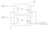
Electrookie, I think 2 FETs (or more) is definitely the way to go. You reduce the resistance losses from connection etc and increase the ability of heat transfer out of the FET silicon to the heatsink etc so the FET silicon runs cooler and more efficient. Most high current switching designs use many FETs in parallel.
I'm not sure why your 10 ohm resistor runs hot. That is what i was saying about testing. Measure the DC voltage on the resistor when running, you can then calc the current passing through the resistor, and the power (heat) wasted on the resistor from ohms law.
I would remove the large output cap altogether. At least for now, for testing. You have 2 oscilloscopes and some multimeters, which is not bad you are well on the way to having a good test setup.
Please don't think that I'm some type of hydrogen expert, I fiddled with hydrogen electrolysis when i was young (late '70's) and found that 1. it's very easy to use electricity to separate water into H and O, and 2. it's quite hard to do it EFFICIENTLY, with very high percentage of the input power going into electrolysis and little converted to waste (heat).
Unfortunately there don't seem to be many people with good hydrogen/electronic skills talking about it, the 2 camps seem to be the overly enthusiastic and sometimes misguided amatuers and the rare uni/pro researchers keeping their mouths shut and their secrets well... secret.
")
Here's how I would go about it;
1. Forget 100 amp setups for now, build a smallish research setup of maybe 10 amps in a nice clear acrylic container. This allows much cheaper and faster changes to the cell and the control electronics, is easier to see it operating, it will be easier to measure, also it won't blow up as much and IF the FET's blow etc it will be much cheaper and quicker to fix.
2. Set up with your oscilloscopes and meters so you can measure the actual electrical power going into the cell, thats the most basic thing you need to know...
3. Test the HEAT going into the cell, this is my personal method for testing it's efficiency and works pretty good. Heat the cell using a known power source and see how hot it gets (above ambient temp) for any given heat power input in watts.
4. Now when operating the cell you know how much electrical power is going into the cell, and how hot it gets (ie a thermometer) tells you how much of that input power is being wasted as heat, the remainder is your conversion power so you can instantly and easily measure the efficiency of your sell in testing.
5. Start testing electrolytes/plate design/frequency/waveform/liquid circulation and any other factors you can think of, and start refining the efficiency of the conversion and the longevity of the plates etc. There is a huge amount of research to be done and not enough people doing it.
Some of the main issues are plate separation and clearance. If the plates are too far apart the cell resistance is high and a lot of energy is wasted as heat. But if the plates are too close together they quickly get bubble fouled with reduces the plate contact with the liquid and it reduces the output and causes other problems like plate hotspots and increases heat buildup.
I like your idea of using reversing DC once the bubbles build up to reverse the plate charge and release the H and O bubbles. You could experiment with that. My personal thoughts are about exploiting the mechanical resonances, even purposely building the plate mounts to allow flexion of the plates at a resonant freq and then tune the freq of the electrical input to vibrate those plates at the resonant freq and clear the bubbles from the plate surface in a way similar to an ultrasonic cleaner bath. If you could shape the plates to force an UPWARD flow, even better still, to get the gas to the top of the cell quicker and bring cool fresh liquid in in a constant circulation. Since you have access to oscilloscopes you can hook a pickup up to a plate, rap it and see the waveform (ie measure resonant freq) on the scope.
Anyway that's my thoughts on the actual electolysis process; converting the electrical input energy to a useful gas fuel at (hopefully) decent efficiency. I'm not at all interested in the whole "HHO/gasoline car fuel economy" side as it always seems to turn into arguments and I'm a motorcycle guy anyway.
")