Continue to Site

Welcome to our site!

Electro Tech is an online community (with over 170,000 members) who enjoy talking about and building electronic circuits, projects and gadgets. To participate you need to register. Registration is free. Click here to register now.

  • Welcome to our site! Electro Tech is an online community (with over 170,000 members) who enjoy talking about and building electronic circuits, projects and gadgets. To participate you need to register. Registration is free. Click here to register now.

Purchasing vintage CPUs

Status
Not open for further replies.
I, sort, of made a microcoded computer as part of a team of 3 in a University lab course. It had 16 words of 16 bits of I-space and 16 4 bit words in D-space and could sort numbers in ascending or descending order. All parts were TTL. Three major parts program counter/branching: me, memory, and some data selectors/compares. I KNOW why the PC counter has to point to the next instruction.
That's very cool...

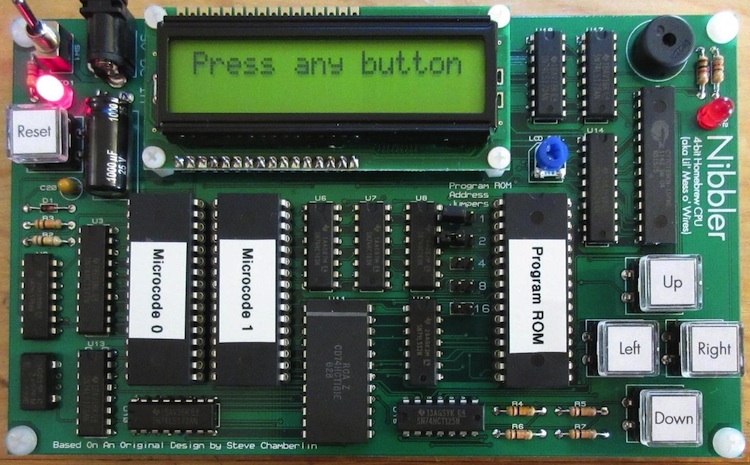
At the risk of going slightly off-topic... Have you seen Steve Chamberlain's 4-bit Nibbler design. It's really quite elegant. Another chap, William Buchholz, actually created and is selling a very nice PCB for it.

Cheerful regards, Mike

nibbler-buchholz.jpg
 
The PIC provides the conditioned 'reset' and the 1-MHz CPU clock signals. During power-up or reset it provides a "blind loader" function. That is, it "pushes" instructions to the 65C02 over the data bus and the 65C02 copies the monitor program and BASIC from PIC Flash memory to 65C02 RAM memory at $E000..$FFFF. The PIC also includes a soft address decoder function that uses a 256 byte decoder map table to map the 'CSx' chip select pins into 65C02 address space (with single page resolution). I mapped the PIC18F26K22 Special Function Registers located at $0F00..$0FFF in PIC data memory into 65C02 address space at $DF00..$DFFF. Basically, the 65C02 has direct access to all 230 PIC SFRs though I only use the SFRs associated with the PIC Serial and SPI peripherals. I can download a new decoder map into PIC flash memory at any time to add a 65C22 or similar devices into the memory map or to change the memory map to mimic retro computers like the KIM-1.

It was more complicated than I thought. So, after the Rom image was transferred to the 64K RAM at E000-FFFF, both PIC and 65C02 are running at the same time, but the 65C02 at a fraction of the speed of the PIC, right?

How does the 6502 access the UART which is in the PIC? Or is the PIC emulating a 6850 ACIA, so the 6502 is using its normally subroutines to send out characters to the UART as if it was a 6850?

How does the 6502 make use of the SFRs in the PIC? Let's say if the 6502 wants to use the timers in the PIC, how would it do it?

I can understand the advantages by adding 2 VIAs to the board and how they work... With the VIA, one can easily add a keypad or interface a PC keyboard to the board.

Allen
 
Last edited:
I want to make my own 8-bit computer. The market might have moved on but I haven't.

I have used the current Atmel AVR 8-bit microcontrollers, but they have their own flash and RAM on the same chip. That's cheating. I don't think I should get any credit for turning one of those into a standalone computer. :)

That's fine with me.:)

I have done single board computers with 6803, 8085 as well as 68B09. I also made a COSMAC elf with the help from the members of the Yahoo cosmac elf group here especially Mr Lee Harts who sold me the 1802 and gave me the static ram free of charge.

I have also made the a 8051 SBC with external RAM and ROM. but if you think that is also cheating, well I cant complain.

I bought my 6502 SBC from Daryl's computer web site here and also the KIM-1 replica here .

If you want to make your own SBC with any of those MPU that you have mentioned. There should be lots of people out there doing them..... anything from a few big chips to a PCB full of TTL/CMOS gates. I think someone was doing a simple computer out of 8088 in Electronic Point forum if you're interested..

Allen
 
Last edited:
Hi Allen:
It was more complicated than I thought. So, after the Rom image was transferred to the 64K RAM at E000-FFFF, both PIC and 65C02 are running at the same time, but the 65C02 at a fraction of the speed of the PIC, right?
Yes, the PIC runs at 64-MHz while generating a 1-MHz clock for the 65C02. Basically, the PIC has sixteen instruction cycles (Tcy = 67.5-nsec) to work with for each 65C02 clock cycle and I use all of them to provide the "decoder" and "I/O" functions at the 1-MHz 65C02 clock rate.

How does the 6502 access the UART which is in the PIC? Or is the PIC emulating a 6850 ACIA, so the 6502 is using its normally subroutines to send out characters to the UART as if it was a 6850?
I'm not emulating an ACIA chip. The 65C02 has direct access to the PIC SFRs which are mapped into a single page in 65C02 address space. The PIC simply "pushes" or "pulls" SFR data to/from the 65C02 over the data bus when it recognizes a 65C02 PIC I/O request. The 65C02 is in complete control and must have its own subroutines for accessing the PIC UART or SPI peripherals. The PIC looks and acts exactly like a memory mapped peripheral IC with 256 registers.

Here's 65C02 code for an early UART echo test. Note that I define the 'PICIO' page to match the memory map and then the PIC UART registers within that page. You should recognize the rest...
Code:
ca65 V2.13.3 - (C) Copyright 1998-2012 Ullrich von Bassewitz
Main file   : monitor_test.s
Current file: monitor_test.s

000000r 1 
000000r 1               .debuginfo +
000000r 1 
000000r 1               .setcpu "65C02"
000000r 1               .macpack longbranch
000000r 1 
000000r 1               ;
000000r 1               ; constants
000000r 1               ;
000000r 1               STACK   := $FC
000000r 1               ;
000000r 1               ;  define PICIO page in memory map and UART registers
000000r 1               ;
000000r 1               PICIO   := $DF00                ;
000000r 1               PIR1    := PICIO + $9E          ; TX1IF & RC1IF flags
000000r 1               TXREG1  := PICIO + $AD          ; uart TX register
000000r 1               RCREG1  := PICIO + $AE          ; uart RX register
000000r 1 
000000r 1               .segment "MONITOR"
000000r 1               .org $FF00
00FF00  1 
00FF00  1               ;***********************************************************
00FF00  1               ;  Reset                                                   *
00FF00  1               ;***********************************************************
00FF00  1 
00FF00  1               Reset:
00FF00  1  A2 FC                LDX #STACK              ;
00FF02  1  9A                   TXS                     ;
00FF03  1               ;
00FF03  1               ;  Display startup message
00FF03  1               ;
00FF03  1  A0 00                LDY #0                  ;
00FF05  1               StartMsg:
00FF05  1  B9 35 FF             LDA Msg,Y               ;
00FF08  1  F0 06                BEQ Loop                ;
00FF0A  1  20 1A FF             JSR Put232              ;
00FF0D  1  C8                   INY                     ;
00FF0E  1  80 F5                BRA StartMsg            ;
00FF10  1               ;
00FF10  1               ;  Echo characters from terminal
00FF10  1               ;
00FF10  1               Loop:
00FF10  1  20 27 FF             JSR Get232              ;
00FF13  1  90 FB                BCC Loop                ;
00FF15  1  20 1A FF             JSR Put232              ;
00FF18  1  80 F6                BRA Loop                ;
00FF1A  1 
00FF1A  1               ;***********************************************************
00FF1A  1               ;  Put232(ACC) subroutine                                  *
00FF1A  1               ;***********************************************************
00FF1A  1 
00FF1A  1               Put232:
00FF1A  1  48                   PHA                     ;
00FF1B  1               Txwait:
00FF1B  1  AD 9E DF             LDA PIR1                ; RC1IF & TX1IF flag bits
00FF1E  1  29 10                AND #%00010000          ; TX1IF = 1 (tx ready)?
00FF20  1  F0 F9                BEQ Txwait              ; no, branch (wait), else
00FF22  1  68                   PLA                     ;
00FF23  1  8D AD DF             STA TXREG1              ; send character
00FF26  1  60                   RTS                     ;
00FF27  1 
00FF27  1               ;***********************************************************
00FF27  1               ;  Get232() subroutine returns character in ACC            *
00FF27  1               ;***********************************************************
00FF27  1 
00FF27  1               Get232:
00FF27  1  AD 9E DF             LDA PIR1                ; RC1IF & TX1IF flag bits
00FF2A  1  29 20                AND #%00100000          ; RC1IF = 1 (rx ready)?
00FF2C  1  F0 05                BEQ NotRx               ; no, branch (exit), else
00FF2E  1  AD AE DF             LDA RCREG1              ; collect Rx char
00FF31  1  38                   SEC                     ; indicate data available
00FF32  1  60                   RTS                     ;
00FF33  1               NotRx:
00FF33  1  18                   CLC                     ; indicate data not avail
00FF34  1  60                   RTS                     ;
00FF35  1 
00FF35  1               Msg:
00FF35  1  0D 0A 4B 38          .byte   $0D,$0A,"K8LH raw test",$0D,$0A,$00
00FF39  1  4C 48 20 72
00FF3D  1  61 77 20 74
00FF47  1 
00FF47  1               ;***********************************************************
00FF47  1               ;  65C02 Vectors                                           *
00FF47  1               ;***********************************************************
00FF47  1 
00FF47  1               .segment "VECTS"
00FF47  1               .org $FFFA
00FFFA  1  00 FF                .word   Reset           ; NMI
00FFFC  1  00 FF                .word   Reset           ; RESET
00FFFE  1  00 FF                .word   Reset           ; IRQ
010000  1 
010000  1
After assembling that code I download it into PIC flash memory over the serial port. Then I press the reset button and the "blind loader" function copies it into RAM at $FF00-$FFFF. Then the 65C02 takes over complete control and jumps to the reset vector.

How does the 6502 make use of the SFRs in the PIC? Let's say if the 6502 wants to use the timers in the PIC, how would it do it?
The entire PIC SFR page at 0xF00..0xFFF in PIC data memory space is mapped to a page in 65C02 memory space so you really just need create "equates" in your 65C02 source code for any of the 230 PIC SFRs you'd like to use. Keep in mind there are very few peripherals you can actually use because I'm using all of the PIC I/O pins to support the Reset/Clock/Loader/Decoder and I/O functions and you also need to avoid using SFRs the PIC uses to support those functions (FSR0 & FSR1).

I can understand the advantages by adding 2 VIAs to the board and how they work... With the VIA, one can easily add a keypad or interface a PC keyboard to the board.
Yes, having some "classic" I/O is important. For example, I'm designing a 64K KIM-1 with just a few chips and a pair of 6532's. The KIM-1 uses one of the 6532's to drive the keypad, display, and a bit-banged serial port. My "soft decoder" function allows me to duplicate the memory map of many classic machines, and by providing direct access to the high performance SPI port on the PIC, allows for some very nice add-ons like keyboard, VGA or NTSC video, SD card file system, etc.

Cheerful regards, Mike

spi modes (small).png
 
Last edited:
Status
Not open for further replies.

New Articles From Microcontroller Tips

Back
Top