Continue to Site

Welcome to our site!

Electro Tech is an online community (with over 170,000 members) who enjoy talking about and building electronic circuits, projects and gadgets. To participate you need to register. Registration is free. Click here to register now.

  • Welcome to our site! Electro Tech is an online community (with over 170,000 members) who enjoy talking about and building electronic circuits, projects and gadgets. To participate you need to register. Registration is free. Click here to register now.

Pulse Delay?

Status
Not open for further replies.
Thanks, I'll have to buy some 4093 chips.


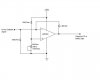
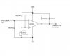
Also, you don't need the opto coupler and 555.

The optocoupler is just something I was learning about, I never used them before and liked the idea of isolating different parts of my circuit. I'll most likely use them for interfacing into a microcontroller later on (for another project).


On the other hand I also like using the monostable and F/F. Obviously there are many ways to tackle my timing needs. I think I will build both, just for learning, and decide later on which circuit to incorporate into my tool.

Thank You All
 
I decided that I will be using an Inverting Schmitt Trigger for sensing if my Power Setpoint voltage is less than 3V or not. I have allready calculated (in my prior circuits) the resistor values I needed but I have been searching online (if I was home I would open my textbook and probably find it faster) and can't find the formula needed to calculate the value of my feedback resistor.

1) Is this something that should be calculated or is it a given value that will work for most circuits?

2) I found online calculators, but I would like to know the formula.

3) Also I would still need a 100kOhm resistor from my 'Power Setpoint signal' to ground, correct?

Thanks in advance
 
Last edited:
stizzswizz said:
I decided that I will be using an Inverting Schmitt Trigger for sensing if my Power Setpoint voltage is less than 3V or not. I have allready calculated (in my prior circuits) the resistor values I needed but I have been searching online (if I was home I would open my textbook and probably find it faster) and can't find the formula needed to calculate the value of my feedback resistor.

1) Is this something that should be calculated or is it a given value that will work for most circuits?

2) I found online calculators, but I would like to know the formula.

3) Also I would still need a 100kOhm resistor from my 'Power Setpoint signal' to ground, correct?

Thanks in advance
I use McMillman's Theorm to calculate the threshold levels. It is a very useful theorm. If you don't know of it and can't find it, let me know and I'll post it. Thevenin's theorm is also very handy.

I don't know why you would need a 100k resistor. If your PSP signal swings between +15V and gnd, then all you need it what I posted.

If the signal was coming from say a relay contact, then you would need a pull down resistor.

I don't have the time at the moment to re-visit your circuits. I'll have a look later.
 
Here's my inverting Schmitt Trigger. I found the formulas I needed and according to them the trigger voltage is 3.01V and it should hold till 2.75V. Of course the circuit will be fine tuned with a 15-turn pot after it is installed in the PECVD tool.
 

Attachments

  • Inverting Schmitt Trigger.JPG
    Inverting Schmitt Trigger.JPG
    16.8 KB · Views: 132
You don't have a load resistor for the comparator to power its output.
You have the inputs of the comparator backwards.
 
audioguru said:
You don't have a load resistor for the comparator to power its output.
You have the inputs of the comparator backwards.

Wow jeezz how'd I miss that? Must of been the 3 chilli-dogs and beer I had for dinner, haha

Here's the updated file....
 

Attachments

  • Inverting Schmitt Trigger.JPG
    Inverting Schmitt Trigger.JPG
    18 KB · Views: 130
2 comments.

The rise time of the output of the S/T (with a 10k pull up resistor) may be too slow for the FF. It won't be a problem if you use a Schmitt NAND.

I still don't know if you need the 100k. What generates the PSP signal?
 
ljcox said:
The rise time of the output of the S/T (with a 10k pull up resistor) may be too slow for the FF. It won't be a problem if you use a Schmitt NAND.

How so? The LM339 is a proper voltage comparator, with open collector output.
 
eblc1388 said:
How so? The LM339 is a proper voltage comparator, with open collector output.
If the S/T is driving the Ck input of a FF, then there will be some capacitance to gnd - ie. the input C of the FF and any stray C.

So say it is 20 pF. 10k & 20 pF gives a time constant of 200 ns.

So, the FF may not change state to Ck transitions - depending upon what the maximum allowable rise time of the FF is.
 
OK. I see.

He can try to use 2K for the LM339 output collector load to ease the problem a bit.
 
The LM339 quad and LM393 dual comparators are very old. They are also low power which means slow.
 
stizzswizz said:
I have some LM311N's, would you recomend another comparator?
The LM311N would be suitable, but you still need a pull up resistor. Whereas, an Op Amp does not need one.

If you want to use a FF, some of them have a Schmitt Trigger in their Ck input so they are not sensitive to the rise and fall times of the Ck waveform.

However, I don't believe that you need a FF solution, combinational logic (as I posted previously) is sufficient provided that the Pos and PSP waveforms are as you posted, ie. once they are stable they remain stable.

The other disadvantage of a FF solution is that it needs a reset.
 
The other disadvantage of a FF solution is that it needs a reset.

Ahh yeah...

I have to pick up some Schmitt NAND gates, so that will be a couple days... I'll make the F/F circuit this weekend though.
 
Status
Not open for further replies.

Latest threads

Back
Top