Timing circuit
Hi unlv0007,
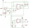
here is your circuit. I doesn't require a PLC, hence no programming. Use you adjustable power supply to supply 35V to the circuit. The circuit includes an adjustable voltage regulator LM317T which you should set to an output voltage of +25V.
Use the CMOS-version of a dual timer IC to make an astable oszillator with a duty cycle of 80%. Time out will be exactly 179.939 seconds. When timing out the astable will trigger a monostable which outputs an exact 100ms 10V pulse.
Do not connect the ground connection of the IC to circuit ground. The ground is floating on +25V. Relative to circuit ground the output, when low is +25V, your desired low level. When triggered the output swings 10V higher and again relative to circuit ground the resulting output voltage will be +35V.
Just in case the parts values are unreadable in the schematic here are the values: R1=240R, R2=82M*, R3=18M*, R4=2K7, R5=1K, R6 910K2*, P1=5K,
C1=100n, C2=1µF/35-40V, C3=2µF2/16V*, C4=10nF, C5=10nF, C6=100nF*
Values marked with an * determine timing. For C3 you might choose a tantalum capacitor.
Hans

")
")
