Electro Tech is an online community (with over 170,000 members) who enjoy talking about and building electronic circuits, projects and gadgets. To participate you need to register. Registration is free. Click here to register now.
Welcome to our site! Electro Tech is an online community (with over 170,000 members) who enjoy talking about and building electronic circuits, projects and gadgets. To participate you need to register. Registration is free. Click here to register now.
Hello
I am trying to design a pulse generator circuit with the profile as shown in attachment. It consists of a 25V pulse of 180sec, followed by 35V pulse of 0.1sec and so on. Please give me the tips on how to build it.
Regards
your sketch indicates a steady +25V level and +35V pulses.
Please clarify.
If so you could use the +25V as ground connection and apply +35V as supply voltage. The difference seen by a timer circuit (astable) would be a 10V supply voltage, well within limits of an NE555 timer chip.
Yes, i need a 35V pulse riding on a steady 25V, but i was in doubt that at the instant when the pulse hits for 0.1 sec, will my power supplies etc be in normal stage and in equilibrium- so that kirchoff voltage law will hold, (which is 25V +pulse voltage) or will there be any oscillations due to the sudden pulse?
Thanks a lot for your help
Regards
unlv007
I have a supply voltage that can provide upto 60V and drive upto 10Amps of current. I am applying the pulses to trigger a chemical reaction and for all electronic purpose, we may model it as non linear resistor. The reaction usual draws <40mA current when i apply a constant voltage of 35V. Please explain how the current drawn by load will affect the state of affairs esp stability considerations when the pulse hits.
I hope that answers your question.
thanks
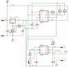
here is your circuit. I doesn't require a PLC, hence no programming. Use you adjustable power supply to supply 35V to the circuit. The circuit includes an adjustable voltage regulator LM317T which you should set to an output voltage of +25V.
Use the CMOS-version of a dual timer IC to make an astable oszillator with a duty cycle of 80%. Time out will be exactly 179.939 seconds. When timing out the astable will trigger a monostable which outputs an exact 100ms 10V pulse.
Do not connect the ground connection of the IC to circuit ground. The ground is floating on +25V. Relative to circuit ground the output, when low is +25V, your desired low level. When triggered the output swings 10V higher and again relative to circuit ground the resulting output voltage will be +35V.
Just in case the parts values are unreadable in the schematic here are the values: R1=240R, R2=82M*, R3=18M*, R4=2K7, R5=1K, R6 910K2*, P1=5K,
C1=100n, C2=1µF/35-40V, C3=2µF2/16V*, C4=10nF, C5=10nF, C6=100nF*
Values marked with an * determine timing. For C3 you might choose a tantalum capacitor.
The output of the LM317 isn't supposed to go below 25V, but maintain a constant output voltage. Using the output as virtual ground and +35VDC input as positive supply the chip will "see" just a supply voltage of +10V, nothing to destroy the chip. Of course it will also sink current, because it has a ground connection, which is just not used to supply the timer circuit.
Why switch a line which is already there? The OP wants a constant +25V voltage level, interrupted by 100ms +35V pulses at intervals of 180 seconds.
The output of the LM317 isn't supposed to go below 25V, but maintain a constant output voltage. Using the output as virtual ground and +35VDC input as positive supply the chip will "see" just a supply voltage of +10V, nothing to destroy the chip. Of course it will also sink current, because it has a ground connection, which is just not used to supply the timer circuit.
The LM317 can't sink current because the output stage is a darlington which can only source current. Some current will be sunk through R1 but it will be subtracted from the minimum load current required by the LM317.
When the output of the 7555 is low it will not be able to source current. Look at the internal schematic of the 7555 it has a complementary pair on the output stage. When the output is lo QH will be off and QL will be on. QL is an N channel MOSFET and won't work when the source is more positive than the drain, in this case it's on a CMOS IC which might go into self distruct mode if you try to use it in this manner.
The circuit probably worked on your similator because it doesn't accurately model the internal components of the ICs. This is why it's important to actually understand what is going on inside those little black boxes when you design a circuit.
Why switch a line which is already there? The OP wants a constant +25V voltage level, interrupted by 100ms +35V pulses at intervals of 180 seconds.
I'm not disputing that. The 7555 doesn't care if the negative rail is 25V and the positive rail is 35V, it will still see a potential difference of 10V.
What I am telling you is that the 7555 will not drive a load connected to a lower voltage than 0V or a higher voltage than Vdd. Trying to drive loads connected to voltages outside the power supply voltage range is a recipe for disaster and will destroy the 7555.
In this circuit, you can either connect the load from pin 3 to 25V or 35V, anything outside this voltage range will cause it to smoke.
The proper way of doing this is to use transistors to control the external loads connected to voltages outside the power supply range.
To have a minimum load at the LM317s output a 1K2 resistor might be connected to ground.
I've some tens of ordinary 555s at disposal. (can easily get more if necessary)To get 7555s I'll have to travel to Bangkok.
Since their internal structure is almost the same (except for CMOS) they should behave similar under the given conditions.
I just chose the 7556 because of the long time delay of 180 seconds, a bit hard to achieve using a 556 because of the minimum threshold current.
The circuit is easiest to build up using one astable and one monostable. The problem is just the high voltage - used for supply it would kill the the chip within no time.
If it's a CMOS IC it'll probably go into destructive latchup, if it's TTL, the base-emmiter junction of the output transistor will breakdown and be destroyed.
If it's a CMOS IC it'll probably go into destructive latchup, if it's TTL, the base-emmiter junction of the output transistor will breakdown and be destroyed.
This site uses cookies to help personalise content, tailor your experience and to keep you logged in if you register.
By continuing to use this site, you are consenting to our use of cookies.

")