Continue to Site

Welcome to our site!

Electro Tech is an online community (with over 170,000 members) who enjoy talking about and building electronic circuits, projects and gadgets. To participate you need to register. Registration is free. Click here to register now.

  • Welcome to our site! Electro Tech is an online community (with over 170,000 members) who enjoy talking about and building electronic circuits, projects and gadgets. To participate you need to register. Registration is free. Click here to register now.

Pspice simulation

Status
Not open for further replies.

bakkis

New Member
Hi,
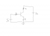
Am trying to learn a simple circuit simulation with Pspice. The circuit is attached. All the base, collector and emitter resistors are 1K. And supplies are 5V. With this i expect the base current to be 42 microamp. But somehow Pspice seems to show 1.19 mA. Am i right in my calculation or there is something i need to do with the Pspice ?
The transistor i use is Q2N3416. Somebody kindly help me asap.
 

Attachments

  • cir1.png
    cir1.png
    11.4 KB · Views: 278
hi,
This is what LTspice shows..
 

Attachments

  • AAesp03.gif
    AAesp03.gif
    25.3 KB · Views: 312
Exactly, how does I(R3) turn out to be 1.19 mA ? Cause if we apply KVL on the input side and having Beta=100(I hope am right here), I(R3) should be 42 microAmp.
 
Exactly, how does I(R3) turn out to be 1.19 mA ? Cause if we apply KVL on the input side and having Beta=100(I hope am right here), I(R3) should be 42 microAmp.

hi,
What do you calculate the input impedance to the Base ???

also the approx Gain of that configuration.??
 
Thank you eric for trying to help me out with this! Input impedance is 1k . The gain i.e Beta is 100 what i suppose it is.
So, with: 5 -IbRb - 0.7 - (Beta = 100)IbRe = 0 yields me Ib = 42 microAmp.
 
Last edited by a moderator:
Thank you eric for trying to help me out with this! Input impedance is 1k . The gain i.e Beta is 100 what i suppose it is.
So, with: 5 -IbRb - 0.7 - (Beta = 100)IbRe = 0 yields me Ib = 42 microAmp.

Hi,
Show me the formula for the DC gain with those values of Emitter and Collector resistors....
 
Am not sure what you mean. Does the gain depend on the resistor values i select. I thought they are transistor dependent.
 
Am not sure what you mean. Does the gain depend on the resistor values i select. I thought they are transistor dependent.

hi,
The circuit gain is a function of the transistor and the Emitter/Collector values
 
True, i agree. But the beta am speaking of is not the circuit gain but the transistor gain.

hi,
As its homework we do not give a direct answer, try this ,,, reduce the Vinput to say 2V and the see what the Ibase measures..

Hint: has your class work covered transistors in saturation ????

EDIT:
Look at this LTS plot note the Vce, the transistor is saturated.
 

Attachments

  • AAesp04.gif
    AAesp04.gif
    29 KB · Views: 273
Last edited:
hi,
This pdf gives a worked example of your problem.

EDIT:
This Sim shows whats happening to the Ib as the Vce falls
 

Attachments

  • Example A BJT Circuit in Saturation.pdf
    90.1 KB · Views: 504
  • AAesp05.gif
    AAesp05.gif
    32.9 KB · Views: 273
Last edited:
Hi eric, thanks for making me realize that i have put the transistor in the saturation. However i still have doubts: My class has started with transistor only a day back, so i dont know if i have come across the saturation conditions yet.
My doubt is : At saturation Ic should be just Vcc/Rc . So should Ie be. i.e Ie = Ic. but at according to the equation at the input Ib doesnt equal to 1.19 mA as suggested by Pspice.

hi,
Did you go thru that pdf I posted, it has a worked example for the circuit type you posted.

Also hint, for the saturation conditions in your circuit you must include the voltage drop across the emitter resistor.

Look at this image, see the RED line showing how the gain falls off at saturation.
 

Attachments

  • AAesp01.gif
    AAesp01.gif
    31.4 KB · Views: 273
Last edited:
Status
Not open for further replies.

Latest threads

Back
Top